By Gayla Broostin, September 2022
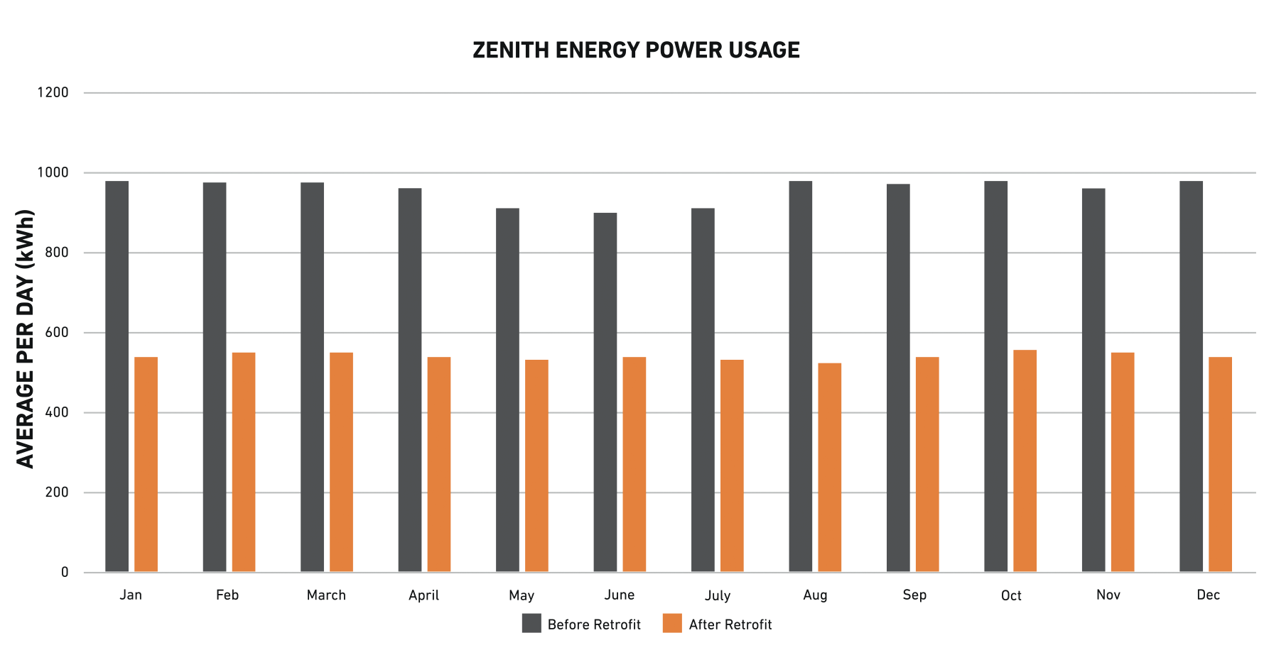
Zenith Energy Power Usage Before and After Zeeco Retrofit
Background
Vapor recovery systems at tank storage facilities have been in use for more than 40 years and were developed to address environmental regulations, primarily regarding the control of Volatile Organic Compound (VOC) emissions generated during the transfer of petroleum products. Vapor treatment may also be required due to odor or toxic exposure concerns.
Over the years, there have been many different evolutions and improvements to vapor control equipment, not only in the design, processes, and efficiency of the units, but also in the ability to achieve lower emissions. This article describes how Zeeco assisted a tank storage facility in making strategic upgrades to its existing Vapor Recovery Unit (VRU). These upgrades improved system reliability while reducing operating costs and carbon footprint.
Situation
Activated carbon VRU systems are widely used in tank storage facilities. An activated carbon unit is essentially a large filtration system. Tank vapors are routed to a bed of activated carbon that removes the hydrocarbons from the vapor by a process called adsorption. Once the bed becomes saturated with hydrocarbons, the bed is isolated and additional vapors are routed to a second, clean carbon bed.
The first carbon bed is cleaned through a process called regeneration by creating a vacuum inside the bed, which causes the adsorbed hydrocarbons to be released from the activated carbon and removed from the bed. One or more vacuum pumps are needed to regenerate the bed and move the vapor stream, now hydrocarbon-rich, to an absorber column. In the absorber column, a hydrocarbon liquid (typically gasoline) contacts the rich vapor stream to condense much of the vapor phase hydrocarbons into a liquid. The absorbent liquid, now containing the recovered hydrocarbons, is returned to the absorbent storage tank. On average, a typical carbon bed VRU can recover approximately 1-2 gallons of gasoline for 1,000 gallons of gasoline loaded.
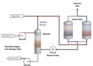
Figure 1 – Activated Carbon VRU Schematic
Challenge
As many loading facilities have aged, it has created opportunities to bring older vapor control equipment up to current standards. There has also been significant growth in gasoline distribution markets, which has driven many terminal operators to seek solutions for expansion of their facilities. More thought is also being given as to how improvements can not only improve operations and capacity but also reduce emissions and carbon footprint.
In 2020, a Zenith Energy tank storage terminal in the Northeastern US contacted Zeeco about problems with its existing activated carbon VRU. The terminal has a storage capacity of nearly 400,000 barrels for biodiesel, butane, distillates, ethanol, and gasoline. Zenith Energy was seeking solutions that would allow them to increase overall loading capabilities and reduce overall environmental/energy footprint and operational costs.
The main issue with this older VRU was the system’s Liquid Ring Vacuum Pump (LRVP) and its auxiliary equipment. As the name suggests, LRVPs rely on a ring of liquid being maintained inside the pump housing. This liquid, often referred to as seal fluid, is a mixture of water and chemical additives needed for freeze and corrosion protection. Frequent maintenance is needed to keep the seal fluid at a proper level and mixture.
The vapors leaving the vacuum pump will contain some seal fluid requiring them to be routed to a separator unit. The seal fluid from the separator must then be routed back to the vacuum pump. A heat exchanger is also typically required to cool the recovered seal fluid before it can be returned to the vacuum pump. See Figure 2 for components of a seal fluid handling system.
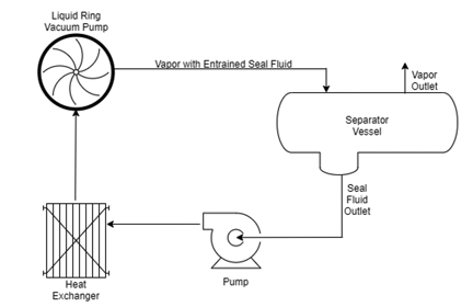
Figure 2 – LRVP Seal Fluid Loop
Common maintenance issues related to LRVP systems include:
- Regular treatment of seal fluid with costly additives
- Monitor and replacement of consumed seal fluid
- Deterioration of seal fluid additives when seal fluid is exposed to ethanol vapor
- Disposal of used seal fluid
- Repair/replacement of heat exchanger internals due to corrosion
- Rebuild of LRVP LRVP required at regular intervals
- Maintenance of seal fluid pump
Another challenge of LRVP operation is that these pumps must operate at the full design speed at all times and cannot be turned down or operated at reduced rates. This leads to higher than necessary power consumption and more frequent vacuum pump maintenance.
The VRU’s LRVP at this location experienced many of the above-listed maintenance requirements. Additionally, because the VRU system used the older LRVP technology that could not be turned down, it had a constant high power usage, even during periods of reduced loading at the terminal.
Because this terminal had only one VRU, maintenance of the system or an unexpected shutdown would force the terminal to cease most transfer operations. This resulted in significant revenue loss and downstream supply chain difficulties.
Solution
The terminal operators asked the experts at Zeeco to propose any solutions that would allow them to increase their loading operation volume and speed, reduce their cost of operations and maintenance, and meet future emissions requirements. The solution would also need to be cost-effective and executed without shutting down terminal operations.
Zeeco’s upgrade plan included a number of recommendations to help the terminal operators meet their goals. The primary change would upgrade the existing LRVP and its auxiliary equipment with a state-of-the-art dry screw vacuum pump. The dry screw vacuum pump is more efficient and eliminates the need for seal fluid and its associated auxiliary separator vessel, pump, and heat exchanger.
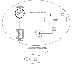
Figure 3 – LRVP Versus Dry Vacuum Pump Components
Additionally, the dry screw vacuum pump can be turned down with a variable frequency drive when full vacuum capacity is not needed. These changes not only improved on the inefficiencies of the previous liquid vacuum pump but also eliminated the additional equipment and services needed to operate the pump, leading to reduced maintenance, utility costs, and downtime.
Zeeco’s Global Field Services Team also recommended the replacement of several leaking valves, upgrading pressure and temperature switches to transmitters, and a new programmable logic controller (PLC) with a human machine interface (HMI) screen to allow easier operation and monitoring of the VRU. Replacement of the valves increased recovery efficiency, while the installation of the new transmitters and PLC enabled more precise control of the process. Programming in the new PLC also added the capability for the VRU to enter into a “power save mode” during periods of low utilization, greatly reducing power consumption and significantly extending maintenance intervals.
The addition of the new PLC and HMI also enabled the system to record historical data such as alarm history, hours of pump operation, outlet emissions concentration levels and pressures, and vacuum and temperature trends. This allowed the generation of more accurate maintenance schedules for individual components of the system based on operating hours and cycles. Alarm information and data trends were also valuable for both identifying operational issues and troubleshooting.
In winter 2020, Zeeco began the retrofit and provided the terminal operators with a ZEECO® Zephyr™; a trailer-mounted vapor combustor unit (VCU) that is part of Zeeco’s extensive rental fleet. The Zephyr is designed to achieve smokeless combustion for a wide range of flow rates with a VOC destruction efficiency of 99% or higher. By utilizing the Zephyr, Zeeco was able to reroute 100% of the VRU vapors to the VCU, where they were safely combusted. This allowed the terminal to maintain safety for personnel and customers, remain within environmental regulations, and kept the terminal running at its usual operating capacity while work on the VRU took place.
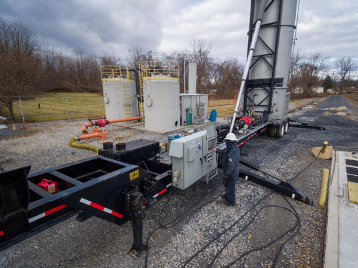
Illustration 1 – Zephyr™ Combustion Unit in Service While Upgrades on the VRU Were Completed
Results
The upgrades to the system resulted in dramatic improvements to the VRU operations, with a higher throughput and increased reliability. The power save mode has also reduced electrical power usage of the VRU by more than 40% (See Figure 3). Emissions levels were also significantly reduced, allowing the unit to already comply with tighter regulations that are expected to be implemented in the future. These improvements are also aligned with current environmental, social, and governance (ESG) criteria. From a financial standpoint, the upgrade was also a success. The return on investment (ROI) for the full retrofit was less than two years.
Zenith took the initiative to improve its VRU system and benefited across multiple areas without requiring any downtime for the facility.
Figure 3: Zenith Energy Power Usage Before and After Retrofit