 Ammonia flaring is on the cusp of change due to the global drive for decarbonisation. Climate-focused countries are enacting legislation to reduce the use of fossil fuels, which can take the form of a direct tax on carbon dioxide (CO2) production at facilities, taxes on end use fuels such as gasoline and diesel, or incentives to use fewer carbon-intensive fuels such as ammonia or hydrogen. Ammonia as a direct-fired liquid fuel or as a transport media for hydrogen within the hydrogen supply chain will find greater utility in the coming years and decades because it has no bound carbon within the molecule.
Due to these societal pressures, momentum has been building in the traditional ammonia industry toward the creation of ammonia using renewable energy sources. Termed ‘green hydrogen’ or ‘green ammonia’, every step in its creation, transport and utilisation as fuel does not require fossil fuels. Full-scale production is only a few years away, with one vendor spending billions of dollars to bring world-class green hydrogen-based ammonia online by 2025.
There are already projects online, or coming online within the next couple of years, that will use ‘blue’ ammonia or hydrogen as a replacement for fossil fuel combustion. Blue ammonia differs from green ammonia in that it is produced through existing fossil fuel-based production methods, but then limits its carbon impact through sequestration and offsets.
What does this mean for the future of flaring? It may be very diverse. Ammonia and/or hydrogen will be found in any facility that makes the switch to a low carbon footprint. Natural gas replaced with hydrogen as a burner or pilot fuel is increasingly requested by end users. Designing combustion equipment to provide effective destruction efficiency (DE) for chemical, petrochemical and gas processing applications presents specific challenges that must be assessed on a ‘per case’ basis. For industries producing chemical compounds where the nature of the chemical itself makes ignition and high DE difficult to achieve, including ammonia, specific flare design practices must be employed to ensure clean and efficient combustion.
Challenges in ammonia combustion
A number of factors contribute to the difficulty of ammonia combustion: it is a nitrogen-based
compound, has low flame propagation speed, low heating value, and low flame temperatures. Meeting these challenges requires specific design criteria for ammonia flares (see Figure 1).
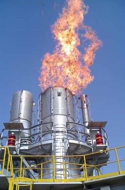
Figure 1. Example of a flare system designed to handle ammonia facility waste gas, featuring a windscreen to assist with effective combustion.
To facilitate the technically-complete combustion of ammonia (99% or higher), it is necessary to restrict the exit velocity of the waste gas to ensure that the ammonia has adequate residence time for high DE combustion. Zeeco has accumulated test data demonstrating a correlation between ammonia flame stability and exit velocity that supports this design philosophy. If a flare system is not designed with this key metric, a higher potential for incomplete combustion and/or an unignited release of the waste gas exists.
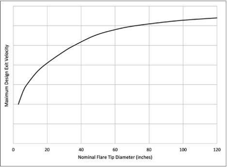
Figure 2. Typical maximum design exit velocity vs nominal flare tip diameter.
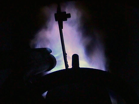
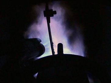
Figure 3. Typical ammonia test flame colour.
For example, Figure 2 illustrates that the maximum design exit velocity for waste gas containing ammonia is dependent upon the flare tip diameter. In general, as the flare tip diameter increases, there is a larger volume of gas and higher heat release from the flame. Thus, designing the flare tip diameter based on controlling the exit velocity assists in maintaining a flame temperature that is higher than the ignition temperature of ammonia, and improving overall flame stability.
Testing performed on 100% ammonia gases by a chemical plant in Houston, Texas, US, further illustrates these points. The flow rate of the gas was varied to evaluate the influence of exit velocity at the flare tip discharge point on the combustion efficiency. Testing was performed on a nominal 12 in. dia. utility type flare tip with a full flame retention ring.
The following were options that were fitted to the tip as part of the evaluations:
- Extended large diameter windshield assembly that enclosed the discharge of the flare tip and the pilots.
- Gas injection assist ring at the flare tip exit point to produce turbulence and increased air inspiration into the combustion zone.
- Multiple pilots (maximum three) were available to determine the impact of ignition flames on the combustion process.
The testing included analysis of the performance of the flare tip assembly using various flows of ammonia, one to three pilots, a gas injection ring, the extended windshield, and combinations of the above. The amount of ammonia present in the plume from the flare was determined using a heated probe that sampled in a position relative to the measured temperature (to ensure that the probe was in the hottest portion of the plume). See the typical ammonia test flame colour in Figure 3.
The conclusions from the testing were:
- Ammonia will burn to technically-complete combustion (99% or higher) if the exit velocity at the flare tip discharge point is kept very low. The acceptable velocity is a function of the nominal flare tip diameter (see Figure 2).
- Higher flare gas exit velocities result in the inspiration of too much ambient air into the combustion zone, which dilutes the ammonia/air mixture to below the combustible limit. Ammonia has a lower explosive/combustible limit that is 16% in air. This is in comparison to most hydrocarbons that have LEL values that are from 1 to 3%. This means that the ammonia and air mixture can easily be diluted to a point where the ammonia will not burn.
- Ammonia needs to have a reliable source of ignition. This is typically provided by a very reliable pilot flame and enough pilots around the perimeter of the flare tip. If the ignition source was removed during the testing, the ammonia would not sustain a stable flame.
- A windshield is very useful in limiting the amount of air inspirited into the ammonia flare gas stream to facilitate ignition of the gases in an area that is protected from crosswinds.
- Burning of the ammonia vapour eliminates any ammonia smell. This process will also produce NOx. Any mole of ammonia will produce one mole of NOx. The temperature of combustion in an ammonia flame is much lower than in a hydrocarbon flame. The NOx produced will typically be colourless nitrogen oxide (NO) and nitrogen dioxide (NO2).
Based on these findings, ammonia can be burned in a flare system with very high efficiency, if the flare system is designed correctly.
Design considerations for ammonia combustion
Extensive testing and validation performed at Zeeco’s testing facility generated innovative advances in design considerations for the burning of ammonia process gas.
Tip waste gas distribution
Commonly, the portion of the flare referred to as the ‘flare tip’ is the upper 10 ft of the flare system. As ammonia waste gas enters the flare tip body, access to air and uniform mixing to promote combustion plays a critical part in fully combusting the compound. To achieve even distribution of the waste gas throughout the entire flare tip body, ammonia flare tips need to include flow distribution devices to properly disperse the waste gas, exposing the waste stream to ignition sources, as well as increasing access to combustion air.
High-stability design, and flame stabilisation
For instance, on typical utility flare tips, windshields are flush with the flare tip exit, and the pilots are arranged on the outer perimeter of the windshield. A flame stabilisation system provides uniform flame stability for initial ignition, as high heating value gas can propagate combustion with ease after initial ignition is accomplished. In contrast, for ammonia combustion, the windshield design should be modified to ensure that the effects of wind are minimised, and interaction between the ignition point, air and fuel is concentrated in this area.
Pilots are placed at strategic locations to increase stability and to be as close to the flare tip perimeter as possible for ignition. Zeeco designs and uses a specialty flame stabilisation system for low heating value gases such as ammonia. With this system in place, the flare tip, pilots, and flame stabilisation tabs are synchronised to promote the highest achievable flame stability. All components interact to provide a highly stable combustion zone, so that the ammonia burns freely, and the flare system achieves high DE.
Exit velocity strategies
Physical behaviour of the gas can be modified when flaring ammonia. As mentioned earlier, the effect of exit velocity on the combustion of ammonia waste gas is dramatic, and design constraints can be put in place to promote stable combustion. Zeeco typically elects to increase the flare tip barrel diameter in conjunction with the use of diffusion apparatuses for ammonia applications. In doing so, ammonia can be slowed to an acceptable exit velocity and diffused throughout the flare tip, promoting proper mixing and stable combustion over a uniform area.
Such systems will need the ability to vent their vessels in the event that a fire occurs in the facility. Therefore, flare systems will need to be able to be sized and designed for these fluids. Whether these gases would need to be vented to a new low-pressure flare system, designed in the traditional way, or within an existing system, would be determined on a case-by-case basis.
Social acceptance of ammonia is the foremost concern of operators using the product. The low odour concentration threshold will quickly alarm operators, and possibly the surrounding communities, of a leak or poorly-performing flare system. Addressing this concern in the FEED stage will start the equipment off on the right path in the crucial first steps.
Discussion
Aside from the combustion design for ammonia facilities, ancillary equipment should be assessed and evaluated. For instance, Liquid Seal Drums (LSD) are commonly used as a safeguard to separate the flare system from the upstream header and equipment. Because ammonia is soluble in water, when a relief stream containing ammonia flows through the LSD, the water will absorb some of the ammonia, forming a corrosive ammonia solution. Often, the LSD is designed as such that all of the water is removed with the waste gas during a flaring event, and LSD is refilled upon completion of the flaring event. In this case, corrosion due to an ammonia water solution is not likely.
However, if there are flow rates expected where the water will not be removed and replaced, further consideration may be needed. Requiring the LSD to be made of specialty materials, coating the inside of the LSD, and/or maintaining the quality of the water by continually skimming and routine cyclical draining/refilling of the water are all possible methods to reduce the effect of ammonia streams through an LSD.
Because ammonia flares are designed to have low exit velocities and low heat releases, noise caused by the flare itself should be minimal. However, ammonia streams are typically high-pressure streams from the upstream equipment in the plant. A portion of this pressure drop will translate to noise that will travel through the plant’s waste stream piping. Because the flare tip is the only exit point for that waste stream, and because of the necessary design characteristic for the flare tip, the tip can act as an amplifier for the noise produced in the upstream piping. Operators experiencing unexpected noise levels at the exit point of an ammonia flare should take into consideration the high amount of pressure drop from the upstream piping or at the relief source.
Conclusion
There are many design aspects to consider when designing flare systems and ancillary equipment for ammonia waste processes. With the influence of more stringent emission regulations on the horizon, progress toward sound inherent design of flare systems to relieve waste will become more crucial. Through further testing and innovation, flare system providers such as Zeeco will have the opportunity to develop new solutions to provide clean, efficient and effective flaring solutions for ammonia and urea plants.