Clayton A. Francis, Zeeco, USA, explains why the greatest environmental impacts from flaring equipment can often seem harmless.
Sometimes things that appear innocuous can be harmful. According to the World Health Organization, more of today’s youth are at risk of hearing loss due to their personal audio devices than from the volume of concerts and music venues.1 It is the commonplace, seemingly insignificant exposure that has the most impact, not, as might be expected, the infrequent blast. This phenomenon holds true in other aspects of daily life, including the impact of certain process equipment.
Community members and regulatory experts have wondered at times if flares are effective at their job of reliable, safe, environmentally responsible disposal of gas. Extensive testing, spanning four decades, has confirmed that properly operated flares do reliably protect the environment as well as the equipment and personnel within an operating facility. Testing has primarily been performed under scenarios of ideal operation of the flare tip and its utility flows. However, factors as varied as insufficient training, lack of process measurement, or other operational hurdles can easily lead to the inefficient and ineffective operation of a process flare.
When considering the added complexity of smokeless flaring technologies, another operational factor is the critical relationship between the flow rates of the flare gas and of the smokeless injection media. When too much steam or air – the two most common smokeless injection media – is applied, the combustion zone can be diluted until combustion efficiencies are reduced or even halted completely. In addition to ensuring that the initial flare design complies with environmental law, it is imperative that the flare design provides protection against the release of unburnt hydrocarbons even at the normal low flow/purge rate for the flare.
An inherent difficulty in smokeless flare technologies is that minimum utility flows of the smokeless injection media are required to protect the combustion equipment from thermal damage. These minimum flows, whether a specified flow from the equipment manufacturer or a pragmatic turndown limitation in the equipment, are somewhat high when compared to the minimum combustible purge gas flowing to the flare. This imbalance between the minimum flare rate and the comparatively large inert smokeless media flow can be devastating to combustion efficiency. Since flares rarely flow at significant upset rates, this troublesome combustion inefficiency at purge rates constitutes the normal, hour-by-hour operation. In this way, the seemingly innocuous comprises the greatest environmental impact from flaring equipment.
The risks of the imbalance between smokeless injection media and flare gas have been studied and identified by researchers and regulatory bodies, leading to regulations in the US that closely monitor and control this ratio to ensure proper combustion even at turndown.2,3 For conventional smokeless flare tip technologies, an increase in combustible purge rates is required in order to meet the regulations for combustion efficiency at normal non-upset operation, leading to increased fuel gas consumption and challenges to existing operating permits. With the revelation that so much negative impact is probable under normal operation, the imbalance between minimum steam injection and flare gas purge rates must be mitigated.
Reducing Steam Consumption
Flares are made smokeless by ensuring sufficient air and entrained oxygen are available and mixed with the hydrocarbon flow so that all carbon-to-carbon bonding is oxidised. With steam flare technologies it is not the steam itself that makes the flame smokeless, but primarily the air propelled and entrained by the steam flow. Advancements in steam flare technology, whether targeting reduced steam consumption or enhanced combustion zone performance at turndown, start by increasing the efficiency with which the air is transported by the steam.
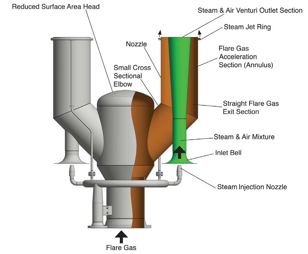
Zeeco engineers developed the SteamForce HC flare technology to resolve environmental issues through an efficient steam injection mechanism. Reducing steam consumption has a multitude of positive effects on operating costs, environmental impacts, and operational compliance. In the new design, a single riser of flare gas is distributed among several steam nozzles. The nozzle assemblies are comprised of an air-educting venturi surrounded concentrically by a flare gas annulus (Figure 1). Each nozzle utilises steam injection as the motive force at its base, and is surrounded at the perimeter by a jet ring to ensure the complete mixing of and interaction between the flare gas and smoke-reducing combustion air.
Steam Injection Technology
In early steam injection technologies, an injector propels ambient air into the combustion zone, most often with a manifold of injectors around the perimeter of the tip. Using steam/air (S/A) tubes increases the air-to-steam injection efficiency by collecting the air with an inlet bell, then transporting that air volume through a tube to the core of the combustion zone. The increased air volume and its deployment to hard-to-access regions of flare gas have been the basis behind most high-capacity steam flare tips for decades. However, two inefficiencies in the system have persisted: the S/A tubes required a mitre or bend to correctly direct the flow, which detracts from the efficiency, and the tube is a consistent diameter across its length (Figure 2, left).
High velocities in the S/A tube when operated at high capacity create drag and pressure drop losses, limiting the overall air delivery for each tube. Several newer technologies are incorporating straight tubes for better performance; however, flow is still constrained and efficiencies limited in the consistent-diameter configuration (Figure 2, right). Venturis are well-known devices and have been used in equipment throughout process plants to compress, propel, or multiply flows.
True venturis have only recently been incorporated into steam flare tips for air propulsion. The expanding cone downstream of the compression section of the venturi avoids the drag and constraint of the straight-diameter tube design (Figure 3).
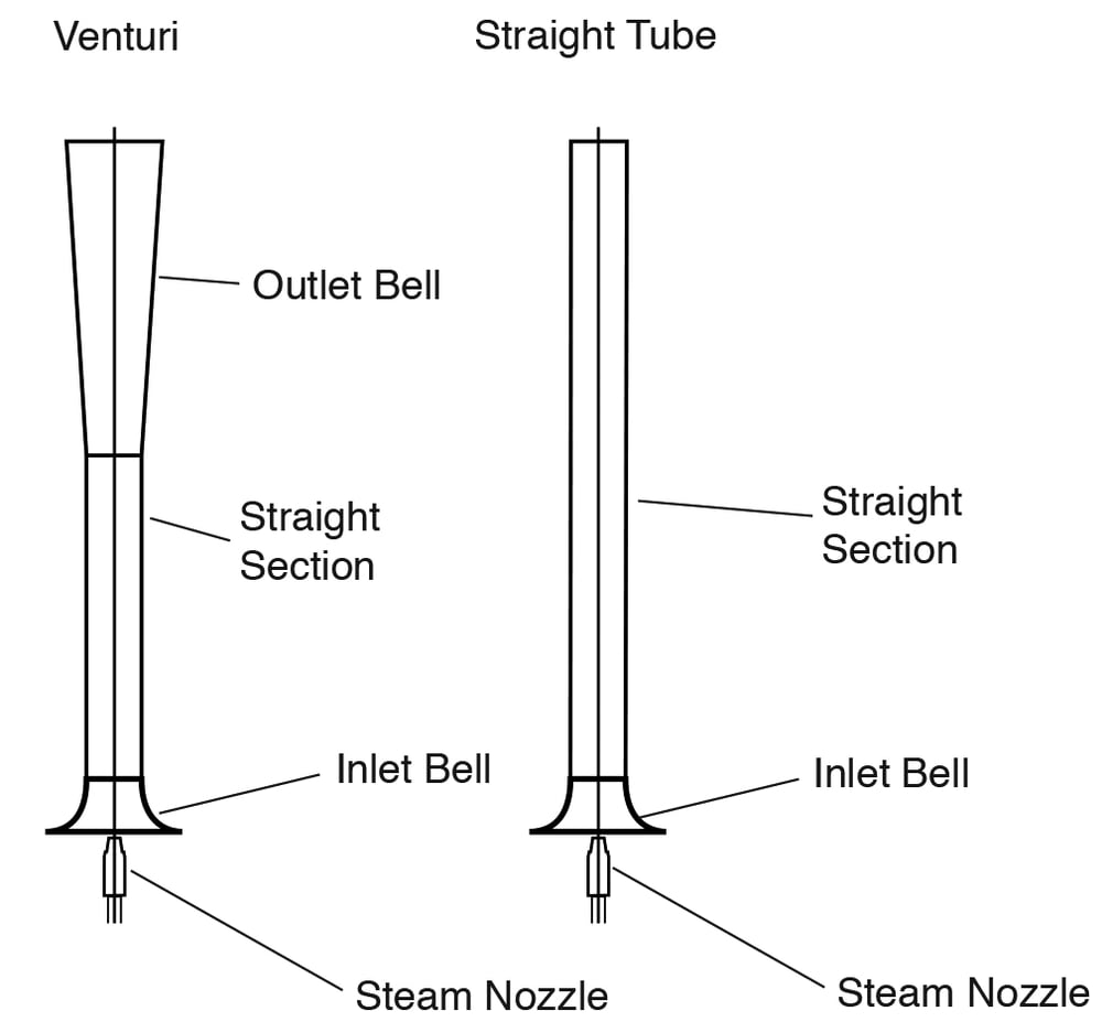
In general, the momentum from the steam ejected from the steam nozzle (on both devices) pulls surrounding air into the inlet bell. The mixture of air and steam then flows through the straight section with the flow becoming developed. In the venturi design, the flow then moves through the outlet bell which gradually increases in outlet area, lowering the pressure, allowing more flow to move through the system. Through empirical testing, this tube design has demonstrated an up to 80% increase in air volume for the same steam flow for a similarly sized S/A tube (Figure 4). This increased air propulsion results in significant steam savings at smokeless (upset) capacities, but more importantly, the reduced steam consumption is applicable at normal daily purge rates as well.
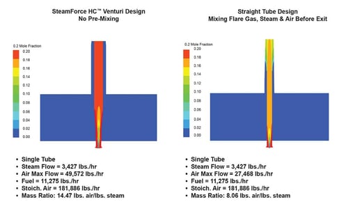
Figure 4. For a steam flowrate of 3427 lbs/hr, the venturi design with no premixing can pull in 49 572 lbs/hr of air compared to 27 468 lbs/hr of air for a straight tube device with premixing of flare gas, steam and air. Furthermore, the venturi device achieved a mass ratio of 14.47 lbs air per 1 lb steam compared to 8.06 lbs air per 1 lb steam for the straight tube device.
Improving access to ambient air supply in flare configurations is a concept proven to work in multi-point ground flares, multiple-armed sonic technologies, and others. With additional injection points, the interaction boundaries between flare gas and available oxygen increase, so more oxygen is pulled into the combustion zone. Only recently has this concept been applied to steam flares, since they have traditionally been a single, large barrel. Apportioning the hydrocarbon flow among multiple nozzle assemblies multiplies the ratio of ambient air in contact with hydrocarbon flows in the flare. This configuration creates an annular flow for the flare gas (Figure 1), i.e. it is surrounded by air on both its interior and exterior perimeters. Encapsulating the gas in this way ensures superior steam and air interaction, further enhancing the smokeless capacity. Ultimately, steam flare technologies are compared by the steam to hydrocarbon mass injection ratio (S/HC) required to make individual gas compositions smokeless. When using propylene as the test gas media, expected S/HC rates are 0.55 for the traditional upper-injection-only steam flare configuration and 0.38 for bent S/A tube designs. By contrast, an annular design requires a rate of 0.25 kg of steam for every 1 kg of propylene burned smokelessly (Figure 5).
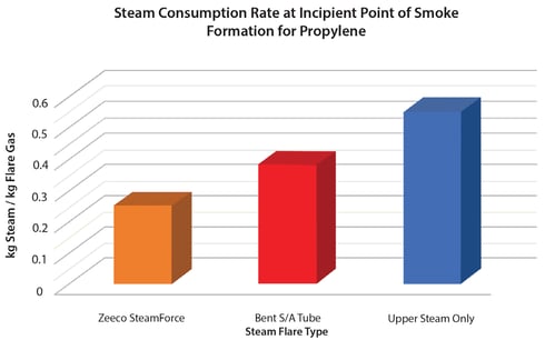
Figure 5. The above shows savings in steam consumption by using a SteamForce HC flare compared to the use of a conventional bent S/A tube or upper steam flare tip.
Flare performance is typically optimised for higher than minimum flows, using velocities and turbulence that are high enough to overcome external influences such as crosswinds. On the SteamForce HC tip, a jet ring is installed around the perimeter of the nozzle to ensure proper interaction between the combustion air and flare gas at minimum flows. Some vendors specify relatively high operating flare pressures, such as 2 – 5 psi, to achieve their promised performance parameters. These technologies rely on the kinetic energy of the gases at emergency or upset rates to optimise performance. However, a multitude of steam flares operate at lower maximum pressures, and the performance of these tips typically suffers drastically at low turndown. By contrast, a jet ring shepherds the shape of the flare flow, ensuring that it correctly interacts with the core of educed air, and maintains the performance of the tip throughout its operational range, most notably at full turndown.
Cost and Operational Considerations
Since flaring events are both infrequent and typically of short duration, the constant-cooling steam flows constitute most of the steam consumed by a flare tip on an annual basis. The cooling flow of steam protects the integrity of the injectors by mitigating the effects of the heat of the combustion zone; this flow and its negative effects are exacerbated in colder climates. With the SteamForce HC design, essentially all of the smokeless air induction occurs at the base of the tip. As a result, the injectors are not as subject to thermal damage. More importantly, the higher volume of air propelled by the venturi tubes further reduces the minimum steam flow required to protect the equipment. Very few venturi nozzles are required to achieve comparable smokeless capacities, again reducing purge steam requirements (Table 1).
As a general approximation of the time a flare spends in purge flow vs a large relief load, the ratio of 95% to 5% has been reasonably used in industry. End users have a record of the maximum steam injection rate and minimum steam flow for the flare equipment, and so a basic analysis between different technologies demonstrates how the operating cost of flare tips can be dominated by the normal, minimum case. Using a general value of US$12/1000 lbs for steam generation highlights the cost saving capability of new steam flare technology (Table 2).
 The method shown in Table 2 for calculating the cost of operation is simplified and captures only the steam supply savings.4 When regulators and users additionally consider the robustness of the combustion zone, sometimes expressed as combustion zone net heating value (NHVcz), an enriching fuel flow must be added at minimum purge rates to ensure healthy combustion. The amount of fuel gas injection required is directly related to the minimum steam rate, so the operational savings of the company’s flaring technology can be magnified further based on fuel costs and local regulations. In particular, this design purposefully does not premix the induced air and flare gas prior to the flare tip exit and pilot location. No premixing means no requirement to include induced air in the NHVcz calculations as described in the US Environmental Protection Agency (EPA) Code of Federal Regulations, Chapter 1, Subchapter C, Part 63, Subpart CC.3 When combustion air is premixed with the flare gas prior to the exit, it has the effect of diluting the combustion zone performance even more than the steam itself. By not introducing combustion air until the flare tip exit, only the steam flow must be enriched, saving the operator significant enrichment fuel gas cost.
Flare tip longevity can also be enhanced. The steam and air injection vectors are vertical, mitigating the possibility of flame capping. Former steam injection technologies had a horizontal inclination to the steam trajectory. When the flare gas flows are at minimum rates, the steam flow imparts more pressure, velocity, and momentum than the combustible flow. The imbalance in flow results in an effective ‘cap’ over the flare tip exit, and this capping often pushes combustion down within the flare tip barrel. This high-temperature, reducing chemical reaction inside the tip causes irreparable damage over time and is a common failure mode of steam-assisted tips. Multiple steam injection sources necessitating multiple control valves can exacerbate this damage because it is possible to apply upper steam injection too aggressively compared to the level applied through S/A tubes. However, when only a single steam source and control is used, the combination of upward injection vectors and single-point control eliminates internal burning of the flare tip and provides greater longevity and value to the facility over time.
CONCLUSIONS
The public largely sees tall, bright flames coming from flare stacks as the greatest health and environmental risk. Ironically, these flames indicate high destruction efficiencies and that the flare is correctly breaking hydrocarbons down to safe compositions. What has been misunderstood is that minute, almost unnoticed flows are the most susceptible to over-application of steam and air. Over aeration is responsible for greater environmental damage, and its rectification results in significant improvements in capital and operating costs. By creating a more effective steam injection mechanism, the combustion zone is enhanced during the predominant use case of low flow while simultaneously using less steam under high flow or upset conditions.
REFERENCES
- ‘Make Listening Safe’, World Health Organization, https://www. who.int/pbd/deafness/activities/MLS_Brochure_English_lowres_ for_web.pdf, (accessed on 14 January 2019).
- ‘Parameters for Properly Designed and Operated Flares’, US EPA Office of Air Quality Planning and Standards, https://www3. epa.gov/airtoxics/flare/2012flaretechreport.pdf, (accessed on 14 January 2019).
- EPA 40CFR 63.671.
- ‘Benchmark the Fuel Cost of Steam Generation’, US Department of Energy, https://www.energy.gov/sites/prod/files/2014/05/f16/ steam15_benchmark.pdf, (accessed on 14 January 2019).