The LNG industry provides for diverse needs ranging from electricity production to feedstock for hydrogen production and a clean alternative for transportation. As the industry expands, technological developments throughout the LNG value chain are paramount to assisting that growth.
At a typical liquefaction facility, natural gas is liquefied at -259˚F (-162˚C). The resulting LNG occupies 1/600th of the volume of natural gas, making it more efficient to transport to major markets where natural gas would otherwise not be easily available. Additionally, LNG is crucial for delivering natural gas to remote locations without access to pipelines.
The LNG industry is composed of various sectors that make up the LNG value chain, including natural gas production, liquefaction facilities, transportation and shipping, storage, and regasification. Many of these facilities require a flare system to handle waste streams due to maintenance, process upsets, or emergency reliefs.
The flare system is designed to safely combust these waste streams to reduce the environmental impact of the facilities. Efficient combustion of the methane produced in a typical facility is important because unburnt methane has a Global Warming Potential (GWP) of 25, compared to that of one of the products of combustion, carbon dioxide, which has a GWP of one. Typically, these flare systems are designed to efficiently handle only gaseous waste streams. API 521 states: “Large liquid droplets and liquid loading can cause smoke, liquid droplets (burning or not burning) to be released from the flare, or mechanical damage.”
Flaring presents a multitude of compliance challenges, such as achieving the permitted visible emission requirements, satisfying noise and radiation requirements, and facility challenges – such as allocating adequate plot space for the flare system and its sterile area. A sterile area has restricted access due to excessive flame radiation or noise levels. Additionally, the flare must be designed to operate across the expected range of relief capacity scenarios. In typical gas flaring systems, liquid process streams, such as those at an LNG facility, would have to first be vaporised or separated using a form of knockout drum prior to sending the gaseous stream to the flare. This can introduce additional complexity and cost to the system.
As shall be explored in the rest of this article, Zeeco has designed and tested a flare that efficiently handles liquid waste streams and thus offers several benefits, such as reduced facility costs, improved plant and personnel safety, and reduced environmental impact.
Successful full-scale testing
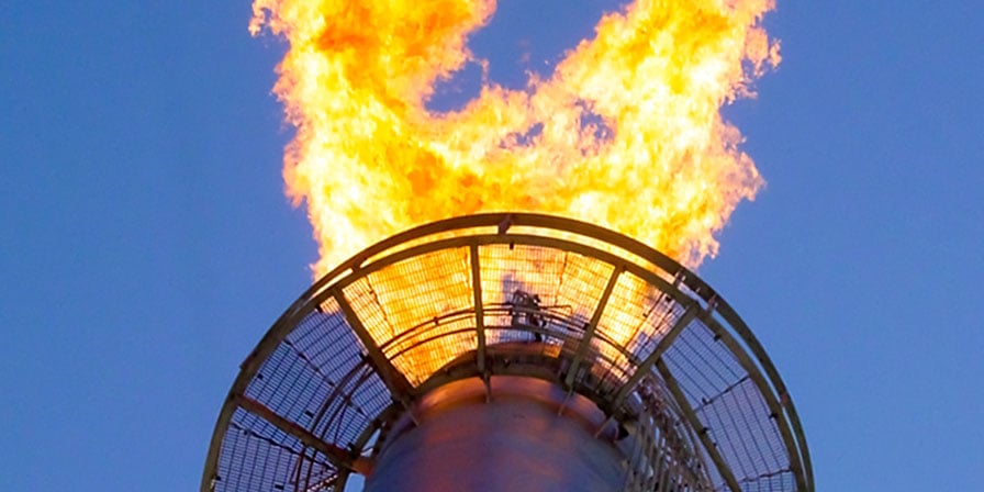
In response to a customer request for a flare system capable of handling liquid waste streams, Zeeco developed a pressure atomised flare system and conducted a full-scale test using LNG at its headquarters in Broken Arrow, Oklahoma, US. The flare test was successful and opened the door to many new opportunities and applications for this technology in the LNG industry.
LNG was delivered to Zeeco in a double wall vacuum-insulated trailer, which was subsequently connected to the test flare header. The trailer’s onboard pump sent the LNG to the flare tip through the stainless-steel header and flare tip. The temperature and pressure of the waste stream were recorded to determine the phase (i.e. gas, two-phase, liquid). When testing began, and the flare header was at ambient temperature, the waste stream was gaseous. As the header cooled, the waste stream transitioned to two-phase and then liquid – while maintaining a stable, smokeless flame throughout the entire process. It is important to note the flare design demonstrated efficient combustion throughout the full range of operating conditions. The flare tip endured extreme conditions and thermal cycling throughout several preliminary tests and then through customer-witnessed customer final testing, with no mechanical damage. In order to provide the most robust liquid flare tip design, Zeeco used a casting to reduce the number of welds in the heat-affected zone and to provide for the mechanical atomisation requirements.
Design considerations
The primary concern with a liquid flare tip is that it can result in a spray of burning liquids that could reach ground level and create a safety hazard. Effective atomisation of the liquid waste stream addresses this issue by breaking the liquid stream into small droplets, thus increasing both the surface area of the liquid and the rate of combustion. Surface tension, viscosity, and density are the primary fluid properties that influence the resulting liquid droplet size and spray pattern characteristics. The flare system is modeled to ensure proper pressure-induced atomisation is achieved for the properties of a given waste stream.
Pressure atomisation means the atomisation is generated by the energy of the waste stream itself and does not require any atomising medium such as steam or compressed air. Another common atomisation method is high-pressure gas atomisation. This is where the fluid is broken into small droplets by injecting air, steam, or natural gas into the liquid stream. The major benefit of pressure atomisation is that it can function without needing additional utilities and corresponding infrastructure, helping to reduce capital and operating costs associated with the flare system.
Flame stability is critical to the safe operation of a flare system and proper destruction of waste streams. A stable flame means the flare remains ignited throughout the operational and environmental design conditions. Lean waste streams (i.e. low heating value) and/or high waste stream exit velocity are typical causes of an unstable flame. Loss of flame stability can result in unburnt waste streams, negative environmental impacts, and safety concerns. The pressure atomised liquid flare system developed for this application uses proprietary Zeeco mechanisms to ensure a stable flame. API 521, Section 5.7.2.4 describes various observations for determining flame stability (i.e a low frequency, pounding noise is associated with an unstable flame as the flame-front pulsates). Based on visible and audible observations recorded during the testing, the flare system maintained a stable flame while transitioning from firing natural gas to two-phase natural gas/liquid and then sub-cooled LNG.
Added benefits
Developments in flare systems can offer a multitude of benefits when building a new facility or retrofitting an existing one. A topic that requires significant consideration is the noise generated by equipment. Blowers, compressors, air dryers, heaters, flares, and other sources all contribute to the occupational noise levels that must be considered to ensure proper personal protective equipment and signage are used when necessary. In some instances, the flare height or sterile radius around the flare is determined by noise limits; therefore, reducing the flare noise level is a great benefit to the health of workers and a potential cost savings opportunity.
In fact, OSHA has reported that “loud noise can create physical and psychological stress, reduce productivity, interfere with communication and concentration, and contribute to workplace accidents and injuries by making it difficult to hear warning signals.” Reducing noise pollution, especially in densely populated areas, can help maintain positive relationships with the neighbouring businesses and communities, which reflects well on the facility. Zeeco’s liquid flaring technologies have been proven to safely dispose of waste streams while generating less noise pollution than traditional gaseous flaring, leading to immediate facility noise reduction and potential longer-term community benefits.
Noise generated by a flaring scenario can be broken into two categories: combustion noise and jet noise. Combustion noise is caused by expansions and contractions of the combustion products due to the local variances in the heat release throughout the flame. These expansions and contractions generate pressure waves that are perceived as noise by the human ear. Jet noise (i.e. vent noise) is due to an increase in fluid velocity through an orifice. Jet noise can be further characterised as turbulent noise, which is pulsations in the flow stream caused by turbulence, and shockwave noise when the exit velocity reaches sonic velocity (i.e. flow becomes choked) at the flare exit.
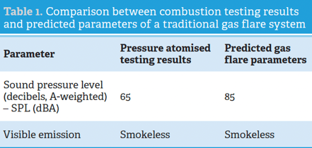
The benefit of liquid flare systems stems from liquids having much higher sonic velocities compared to gases. For example, the speed of sound in methane gas is 925 ft/sec. (at -259˚F) whereas in liquid methane it is 4658 ft/sec. (at -274˚F). Also, liquids have higher densities than gases, meaning the exit velocity for liquids is less at the same mass flow rate. Considering the higher sonic velocity for liquids and the lower exit velocity for a given mass flow rate, liquid flare systems generate minimal jet noise. This was confirmed by the flare testing performed by Zeeco, which showed that the pressure atomised liquid flare produced significantly less noise than a gaseous flare at the same mass flowrate. Table 1 shows a comparison between the pressure-atomised liquid testing results and the predicted results of a traditional gas flare system.
Another consideration for facilities is the equipment’s footprint and associated costs of the equipment such as piping, supports, and other ancillary items. For example, reducing pipe diameter has numerous benefits, including decreased total piping material weight; significantly reduced pipe rack requirements; easier installation – due to there being less material to handle and less welding due to smaller pipe diameters; decreased size of accompanying items (i.e. valves and flanges); and a reduced overall equipment footprint. The benefits of decreasing pipe diameter also apply to the flare riser which can reach several hundred feet tall, with supply reductions and wind area reduction further reducing the flare system capital cost. As previously mentioned, due to its greater density, liquid waste streams can use smaller diameter pipe compared to gaseous streams for a given mass flow rate.
To put these potential system savings into perspective, a comparison of an LNG system for liquid flaring and an LNG system for gas flaring is a useful illustration. Using a flow rate of 700 000 lb/hr, the estimated cost for an LNG system for liquid flaring is US$750 000. Meanwhile, an LNG system for gas flaring under the same process conditions is estimated at US$900 000. These costs are estimates for the supply of the flare system only and do not include savings from headers and header supports. In addition to the capital cost savings, pressure atomised liquid LNG flaring systems can reduce noise and overall cost of ownership over time.
Conclusion
Technological developments are crucial to maintaining the progress made by the LNG industry over the past 50 years, as well as fuelling its future development. The pressure atomised liquid flare system for LNG, as designed and tested by Zeeco, is one of the latest developments contributing to the advancement of the industry, offering an LNG flaring solution capable of handling sub-cooled natural gas reliably within severe, cryogenic operating conditions. As LNG continues to grow in popularity as a clean and economical alternative to other fossil fuels, further advances will inevitably be made, propelling the LNG industry onwards into its next stages of development.
Bibliography
- ‘Pressure-Relieving and Depressuring Systems: API Standard 521’, American Petroleum Institute, (2014).
- ‘Liquefied Natural Gas: Understanding the Basic Facts’, US Department of Energy, (August 2005).
- ‘Safety and Health Topics | Occupational Noise Exposure - Health Effects | Occupational Safety and Health Administration”, United States Department of Labor, www.osha.gov/SLTC/ noisehearingconservation/healtheffects.html.
- ‘Atomization Concept and Theory’, GRACO, wwwd.graco.com/ training/concept_and_theory/Atomization%20v2.pdf.
- VASILYEV, A, Y., et al., ‘Classification of Atomization Devices’, Journal of Physics: Conference Series, vol. 1359, (2019), p. 012131., doi:10.1088/1742-6596/1359/1/012131.
- Climate Change Connection, climatechangeconnection.org/ emissions/co2-equivalents/.
- BIES, D.A., and HANSEN, C.H., ‘Engineering Noise Control Theory and Practice’, Spon Press/Taylor & Francis, (2009).
Download