A burner retrofit has delivered more robust operation with reduced NOx emissions from a crude process furnace.
Zeeco recently had the opportunity to work with a large refinery on the US Gulf Coast on a burner retrofit project for a crude heater process furnace. The existing burners were a conventional emissions design using carbon steel rotary registers designed to operate on ambient, forced draft combustion air. There was a total number of 16 existing burners installed in the furnace, utilising a common air plenum.
The refinery sought to replace the existing burners because of operating challenges:
- The original burner rotary registers had become inoperable and were frozen at one setting.
- Even after returning the registers to an operable condition, they would again freeze in a short period of time due to the carbon steel material oxidising in the high humidity and salinity of Gulf Coast air.
The existing burners used a multiple tip design for gas firing operation, and also had the ability to fire liquid fuels. During discussions prior to the start of the project, the refiner indicated that it would be removing the capability for liquid firing. The refiner also wanted to employ a new fuel gas burner design that would be easier to maintain and produce less NOx.
There would be insufficient time during the planned turnaround when this retrofit project was scheduled to occur to perform any floor modifications to the furnace. Therefore, the proposed solution could not involve any heater floor and refractory modifications, and the retrofit burners would need to fit the existing burner mounting in the furnace.
As a summary, the following were the main priorities and design objectives for the crude heater burner retrofit:
- Use a burner register design that would mount in a common air plenum
- This burner register design must be constructed of a material that would resist rusting in the Gulf Coast atmosphere
- The burner register must be sufficiently robust that it could be operated for the foreseeable future without freezing in place
- The burner that would be supplied must fit into the existing furnace refractory floor opening without any floor modifications
- It was the preference of the refiner to use the same quantity of burners (16) to prevent any floor modifications that would make the project economically unfeasible
- The burner must be easy to maintain for operations/maintenance personnel
- The burner should be designed to provide some reduction in NOx emissions versus the existing conventional emissions burners currently installed in the furnace.
After reviewing all of the mechanical requirements from the refiner, along with all of the process requirements for the burner operation, the GB Single Jet burner from Zeeco was selected as the best solution.
GB Single Jet Burner Design Features
The GB Single Jet burner is based upon an existing conventional emissions burner design, with the incorporation of staged air, staged fuel, and internal flue gas recirculation (IFGR) to reduce emissions. The burner uses a single gas tip firing on a cone assembly, but instead of firing on the centre line of the burner, the tip and cone are offset to fire nearer to the inside diameter of the burner tile (see Figure 1).
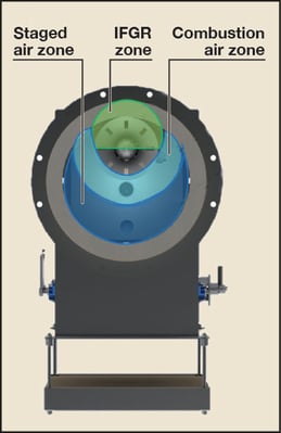
Figure 1. Burner throat of a typical GB Single Jet burner showing the different combustion air
and IFGR zones of the burner.
The offset gas tip and cone design allows the burner to stage a percentage of the combustion air in the burner throat and generate IFGR into the base of the burner flame. The location of the gas tip and cone assembly increases the amount of IFGR and helps create a stable low pressure zone to maximise the amount of IFGR into the combustion zone. The introduction of IFGR allows for the peak flame temperature in the flame core to be reduced dramatically. As shown in Figure 2, reducing the peak flame temperature reduces thermal NOx emissions. The GB Single Jet burner configuration’s single tip, offset design simplifies operation and maintenance and reduces emissions when compared to a raw gas conventional emissions burner.
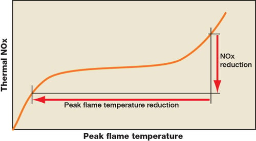
Figure 2. Peak flame temperature versus thermal NOx production.
Another design feature of the GB Single Jet burner is the compact size of the burner components. Most low NOx burners utilise a larger number of gas tips, complex tile geometry, and flame holders in order to provide a stable burner flame that still meets emission requirements. The GB burner uses only a single gas tip and cone assembly to achieve the emissions requirements. Also, the tile geometry for this burner is normally a straight-sided tile. In addition to being a more cost effective tile shape, it is a smaller tile footprint than that required for a typical low NOx burner. The smaller tile footprint simplifies retrofit applications into existing furnace burner mountings by removing the need for expensive floor steel and refractory modifications.
Mechanical Features of the Burner – Different Air Register Design
From discussions with the refiner, the main mechanical feature on the burner that required an upgrade in design and materials of construction was the air register assembly. As indicated earlier, the existing rotary air register assembly had become frozen in position, preventing the refiner from operating the burners as designed. The refinery’s maintenance personnel had no way of controlling the burners to achieve long term, efficient operation of the furnace. Also, the frozen rotary registers presented a safety hazard, as some burners had the rotary registers frozen in a position where there was insufficient air for complete combustion entering through the burner.
After meeting on site with refinery personnel, the Zeeco burner design team selected an air register with rotary inlet vanes instead of rotary registers for the replacement burners. The rotary inlet vane provided the best design because it would fit into the existing furnace floor opening for the burner and did not rely on a rotating register mounted to a stationary air register. The rotary inlet vanes would rotate about the centre line of the vane on a stationary cylinder inside the common air plenum. This stationary cylinder would be welded to the burner front plate, where the register shafts, linkage arms, connecting gears, and vane shaft bearings would be mounted (see Figure 3).
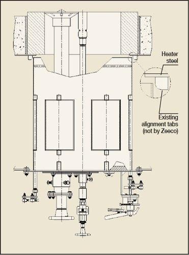 Figure 3. Peak flame temperature versus thermal NOx production.
Six inlet vanes were chosen for this design as this provided the optimum open area to flow sufficient combustion air and excess air to insure complete combustion of the fuel. As shown in Figure 3, there is a single damper handle provided on the burner to allow for simultaneous adjustment of all register inlet vanes on the burner. Each inlet vane has a damper shaft that is welded to the vane centre line, and this damper shaft projects through the burner front plate. Each individual damper shaft is connected to the damper handle by the use of linkage arms and gears. Each damper shaft protrusion also has a packing bearing that can be lubricated to insure smooth operation of the vane inlet damper over the lifetime of the burner. Figure 4 shows the bottom view of the burner front plate to further illustrate the configuration of the vane inlet register and the linkage arms driving the movement of the register. It is important to note that this is the view of the burner front plate looking directly up from below when it is mounted into the common air plenum assembly.
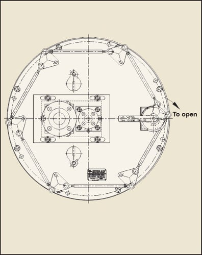
Figure 4. View of the burner front plate, as seen from below when mounted
into the common air plenum assembly.
All of the vane inlet registers can be operated easily with the single damper handle assembly provided (see Figure 4). The damper handle assembly is spring loaded and can be locked into place. The damper has 32 individual settings between full open (setting number 8) and full closed (setting number 0). This would provide the refinery’s operations personnel with a better method of controlling combustion air entering the burner, and the individual lockable settings would allow 52 Revamps 2017 www.eptq.com for consistency in the combustion air register settings of all 16 burners in the furnace.
Upgrade to Materials of Construction
While the improved burner register design using the vane inlet register would provide a more robust solution, the refinery was still concerned that without upgrading the materials of construction they could face similar register freezing problems in the future. The original burner rotary registers were constructed from cast steel and carbon steel sheet metal. Neither surface was painted since they were internal burner components installed inside the existing common air plenum. This resulted in the existing burner register design oxidising and rusting in the high humidity and salinity atmosphere of the Gulf Coast of the US.
After discussions with the refiner, the burner design team selected 304 stainless steel as the material of construction for the stationary air cylinder, the inlet vanes, and the inlet vane damper shafts. Austenitic stainless steel of this type has an inherent resistance to rust and oxidation, removing the need to paint, or coat, any of the internal vane inlet air register components and lowering maintenance costs in the future.
Burner Tile Design for Easy Retrofit
The GB Single Jet burner is generally smaller in physical size than other low NOx or ultra low NOx burners with the same heat release and air side pressure drop. This burner size easily matched the necessary mounting dimensions for the burner front plate to the common air plenum.
After reviewing the physical installation of the existing burners, the project team decided to reuse the existing tile mounting plate already in place on the furnace floor. This existing tile mounting plate had installed alignment tabs to help position the stationary cylinder with the vane inlet registers to be properly centred with respect to the furnace floor opening and burner tile.
The only issue the project team faced was that the smaller footprint of the chosen burner meant that while the outside diameter of the existing tile was approximately 27in, the burner tile required for the new burners would only have an outside diameter of 23in. Even with the smaller burner tile, the GB Single Jet burners would be using the same amount of pressure drop as the existing burner. If changes were made to the diameter of the burner throat to accommodate using a standard tile size, it would reduce the pressure drop across the burner, making it harder to control the burner combustion airflow and excess air. In order to solve this issue, the team elected to make the cylindrical burner tile of the GB burners twice as thick as required to maintain the same outside diameter as that of the existing burner tile. Using a thicker burner tile would allow the refinery to replace the existing burner tile with the new burner tile with no modifications required to the furnace floor. Maintaining the same outside diameter of the burner tile was necessary to complete the retrofit within the three-week turnaround period allotted for this furnace. The tight schedule overall meant that any time that could be saved in the project needed to be saved.
One additional area where the refinery and burner manufacturer worked together to reduce the time necessary to bring the furnace back to full operation was in the tile refractory material of construction. Zeeco had planned on using a water based 60% Al2 O3 (alumina) refractory material for the burner tile. While this material does have a service temperature of 3000°F (1650°C), the refinery was concerned that the dry-out time necessary to reach ceramic bond of the refractory would hamper the time to reach full load in the furnace after the turnaround was completed. The project team selected a phosphate bonded refractory material for the new burner tile. The phosphate bonded burner tile does have the same alumina content, 60% Al2 O3 , and the same service temperature, 3000°F (1650°C), but it does not require any pre-firing of the refractory material once it is cast into shape. The phosphate bonded material produces an exothermic reaction during the casting process, and this exothermic reaction heats the refractory material to ceramic bond so that the burner tile does not require any additional dry-out time. The furnace temperature can be increased after turnaround based on the process requirements of the refinery.
Adjustability of the GB Single Jet Design
One of the main lessons the project team had learned from previous burner retrofits into any furnace is that there must be some mechanical adjustability of the burner once it is installed. Most refineries select furnaces for retrofits that have been in continuous service for many decades. While refinery operations personnel are very diligent in maintaining the external areas of the furnace, the internal operating areas of the furnaces are only inspected and maintained during turnarounds. Most of these refineries are now planning turnarounds every 2-5 years, so opportunities to correct any damage to internal areas are reduced.
A common retrofit challenge is that the floor refractory in operating furnaces will not be even at each burner location. Over several decades of service, the floor refractory levels can degrade, and only some areas are partially repaired during turnaround opportunities. As a result, project teams must plan for, and be able to mechanically adjust, each individual burner to the specific refractory thicknesses at each burner location. If no mechanical adjustment is provided, then it is not possible to optimise the operation of the burners to achieve low NOx emissions. If the furnace refractory differences are too severe, it is possible that the stable operation of the burner could be affected as well.
The GB Single Jet burner has three areas of adjustment: the first adjustment is an additional set of mounting holes on the burner front plate; the second adjustment is mounting hubs for the main fuel gas riser and pilot for vertical adjustment; and the third adjustment is a sliding mounting plate for horizontal adjustment of the main fuel gas riser and pilot.
In Figure 4, it is easy to see the location of the additional mounting holes for the burner front plate. Having this adjustment provides a solution to the challenge presented when the existing mounting bolts in the air plenum have become damaged during the removal of the existing burners. By including an additional set of mounting holes on the front plate that are offset at a small angle from the existing mounting bolts, maintenance personnel can install the new burners even if this problem occurs. Instead of drilling out the existing, damaged mounting bolt, a new mounting bolt can be installed in the new location. It is much faster to shear off the existing, damaged mounting bolt and install a new mounting bolt than to repair every damaged mounting bolt.
The second area of adjustability is the inclusion of mounting hubs and set screws to adjust the vertical location of the main fuel gas riser and pilot assembly. Figure 5 shows the location of the mounting hubs and the set screws that can be loosened for easy vertical adjustment.
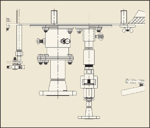
Figure 5. Set screws and mounting hub vertical adjustments for the main fuel gas riser and pilot assembly.
By providing the set screws and mounting hub, it is possible to mitigate the effects of uneven areas of floor refractory or heater floors warped from decades of service. This makes sure that the installation team can accurately set the location of the cone assembly, main fuel gas tip, and pilot location for optimum burner operation and reduced NOx emissions. To prevent inadvertent misalignment during future maintenance activities, the manufacturer recommended that the refiner allow the installation team to tack weld the mounting hubs to a static setting once each burner was set properly during the turnaround. Again, doing so would prevent accidental vertical movement of the fuel gas riser, cone assembly and pilot location during future maintenance activities.
The third area of adjustability is the inclusion of a small burner fuel gas riser and pilot mounting plate that has slotted holes on the burner front plate. This allows for the main firing mechanism of the burner to be adjusted in the horizontal direction without changing the firing geometry between the main fuel gas riser, cone assembly, and the pilot location. Figure 6 shows this small mounting plate provided on the burner.
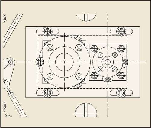
Figure 6. Burner fuel gas riser and pilot mounting plate horizontal adjustment plate.
This smaller front plate mitigates any irregularities in the mounting location in the common air plenum versus the location of the heater floor opening for the burner. If the two openings in the common air plenum and heater floor are not concentric, then the mounting nuts on the smaller, sliding front plate can be loosened to adjust the gas riser, cone assembly, and pilot to the proper location at the inside diameter of the burner tile. While the burner will operate satisfactorily with the gas riser, cone assembly and pilot located away from the inside diameter of the burner tile, operating it in that way will increase thermal NOx emissions as the burner will have reduced IFGR into the base of the burner flame. Providing the adjustment shown in Figure 6 allows the flexibility needed to complete a retrofit into existing burner spacings in a furnace floor within a short time frame but without sacrificing NOx performance.
Ease of Maintenance
The last item for the burner retrofit was a request from the refiner to utilise a burner that would be easy to maintain. The GB Single Jet design uses a single gas riser assembly with gas tip. This design is very similar to the conventional emissions burners that are typically familiar to most refinery maintenance and operations personnel. This similar design makes it easier for refinery maintenance personnel to utilise existing cleaning procedures. Removal of the fuel gas riser is easily accomplished by removing four mounting nuts and removing the fuel gas riser from the burner. Figure 7 shows the fuel gas riser and gas tip that require routine maintenance and cleaning.
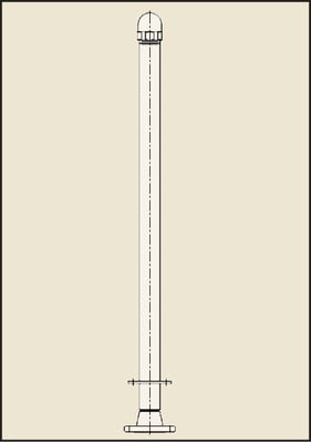
Figure 7. Providing a single, easy removable fuel gas riser and gas tip significantly reduces the maintenance time required versus time to maintain a multiple gas tip low NOx emissions burner.
Conclusion and Lessons Learned
The retrofit was carried out in late 2016 and the burners provided have been operating without any mechanical issues. The refinery personnel are satisfied that the burners provided a more robust solution with satisfactory operation.
The refinery was able to carry out the burner retrofit within the three-week turnaround timeframe with a few days to spare. No modifications to the floor refractory were required and using the increased thickness of the burner tile allowed for all 16 tiles to be installed during two shifts of work. The refinery did have to utilise approximately 25% of the additional mounting holes on the burner front plate due to damaged mounting bolts in the common air plenum. Zeeco was on site during the final portion of the turnaround to help adjust the vertical and horizontal location of the fuel gas riser, cone assembly, and pilot for optimum performance and thermal NOx emissions. Feedback from the refiner indicates that there is no evidence of any rust or oxidation on the new vane inlet register assemblies, and operations personnel are able to easily adjust the vane inlet air registers for optimum burner performance. Even though NOx reduction was a secondary requirement, the refinery is reporting that the new burners are operating at half the historical NOx emissions of the previous burners. The refiner is satisfied with the burner performance, has a burner that is easy to operate and maintain, and has reduced thermal NOx emissions from the crude heater.
Ryan D Roberts is a Senior Applications Engineer with Zeeco, Inc. He has spent the last 20 years of his career in the Burner Group, and is currently focusing on the retrofit of existing burner installations. He holds a BS in mechanical engineering from the University of Oklahoma.
Download Article