As increasingly stringent NOx requirements are implemented around the world, end users with fired heaters and industrial boilers are forced to update existing fired equipment to meet regulations. Both new applications and retrofits projects may need Ultra-Low NOx or Next Generation Low NOx Burners to meet the ever-tightening emissions requirements. Recently, Zeeco accepted a retrofit challenge to replace 34 conventional burners at a European refinery with a capacity of 11.5 million tonnes per year. The project objectives were to significantly reduce NOx production, increase combustion efficiency, and eliminate flame impingement on the heater process tubing. Zeeco’s GLSF Min-Emissions Ultra-Low NOx Burner was the selected equipment to achieve these goals.
Background
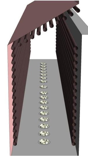
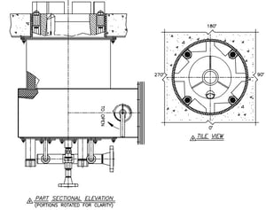
The existing raw gas burners installed on the client’s forced draft, pre-heated air, crude heater were proving troublesome. The existing burners were producing NOx values well above 200 mg/Nm2 [100 ppmv]; the combustion in the firebox was poorly distributed across the burners; and in several places, the burner flames were long enough to impinge on the short heater roof tubes, causing process tube coking. To eliminate these issues, the client decided to retrofit the crude heater with Ultra-Low NOx burners. Zeeco was selected to provide 34 GLSF-8 Round Flame, Min-Emissions Ultra-Low NOx Burners. The heater is a twin-celled cabin heater with a sloped roof leading to a common, central, convection section. There is one row of 17 burners installed in each heater cell. A rendering of the cross-sectional view of the heater can be seen in Figure 1 below along with the original heater drawing for reference.
Project Phases
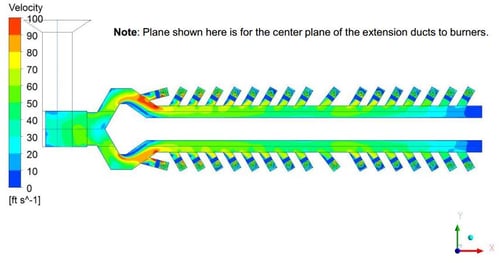
This project was completed in three main phases. The first phase included the design and drafting of the burners, and the completion of two geometry models for Computational Fluid Dynamics (CFD) simulation. The two CFD models included the existing forced draft, preheated air ducting system, and half of the heater firebox geometry with the row of 17 burners. Phase two included the completion of a combustion test performed at Zeeco’s combustion testing facility in Tulsa, Oklahoma. The test was conducted with two GLSF-8 Min-Emissions burners installed in one of Zeeco’s cabin-style heaters. Phase three included the installation and commissioning of the burners on site, as well as site acceptance emissions measurements.
Phase One – Burner Design and CFD Modeling
Phase Two – Combustion Testing
Phase Three – Installation & Site Acceptance Testing
Project Review
The three phases of the project required time and careful technical engineering design to achieve the successful results reported by the end user since start up. The scheduling of the project needed to be maintained at a constant pace of progression in order to engineer the
customized burner design, generate the CFD results and reports, set up and execute the combustion test, manufacture and deliver the equipment, and finally, execute a successful install and start up. Overall, the project was completed in 44 weeks from start to finish. The equipment was delivered as scheduled, before a scheduled major site turnaround.