INTRODUCTION
This paper explores solutions to challenging radiant wall burner retrofit applications. For example, a significant challenge facing the combustion industry today is being able to bring old technology into compliance with new regulations without sacrificing performance. Many existing radiant wall burner applications are challenging to retrofit for lower emissions with traditional radiant wall technology due to burner proximity, flame interaction, elevated temperatures, and fuel variances, including lower-carbon fuels, e.g., hydrogen. In this paper, Zeeco shares how we used physical testing together with CFD to address these challenges. We explore the use of our approach to drive innovation and create new product developments, as well as share lessons learned and project outcomes.
BACKGROUND
The purpose of the Zeeco Radiant Wall Burner Development was to increase the ability to operate with high hydrogen fuels in order to lower CO2 emissions, lower NOx emissions, increase the projected service life of the tip, and to reduce expected maintenance costs. To achieve these goals, the gas spud, venturi, and tip designs were all revised to provide a simple overall solution. Schematics representing the RWSF burner with both internal flue gas staging as well as external flue gas staging are shown in Figure 1 and Figure 2, respectively.
The RWSF burner with internal flue gas staging, shown in Figure 1, is used for applications with a close burner to burner spacing and for high hydrogen applications. The staged fuel gas provides a richer fuel mixture at the end of the tip compared to the entrance of the tip, which allows for some NOx reduction while producing a more compact flame shape. The simple design allows for easy maintenance since the fuel gas spud, complete with an internal staged fuel gas riser, can be removed at the same time from the end of the burner. Note that the slots in the tip are horizontal with respect to the end of the tip.
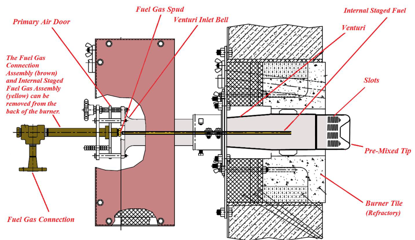
Figure 1. Zeeco RWSF burner with internal fuel gas staging
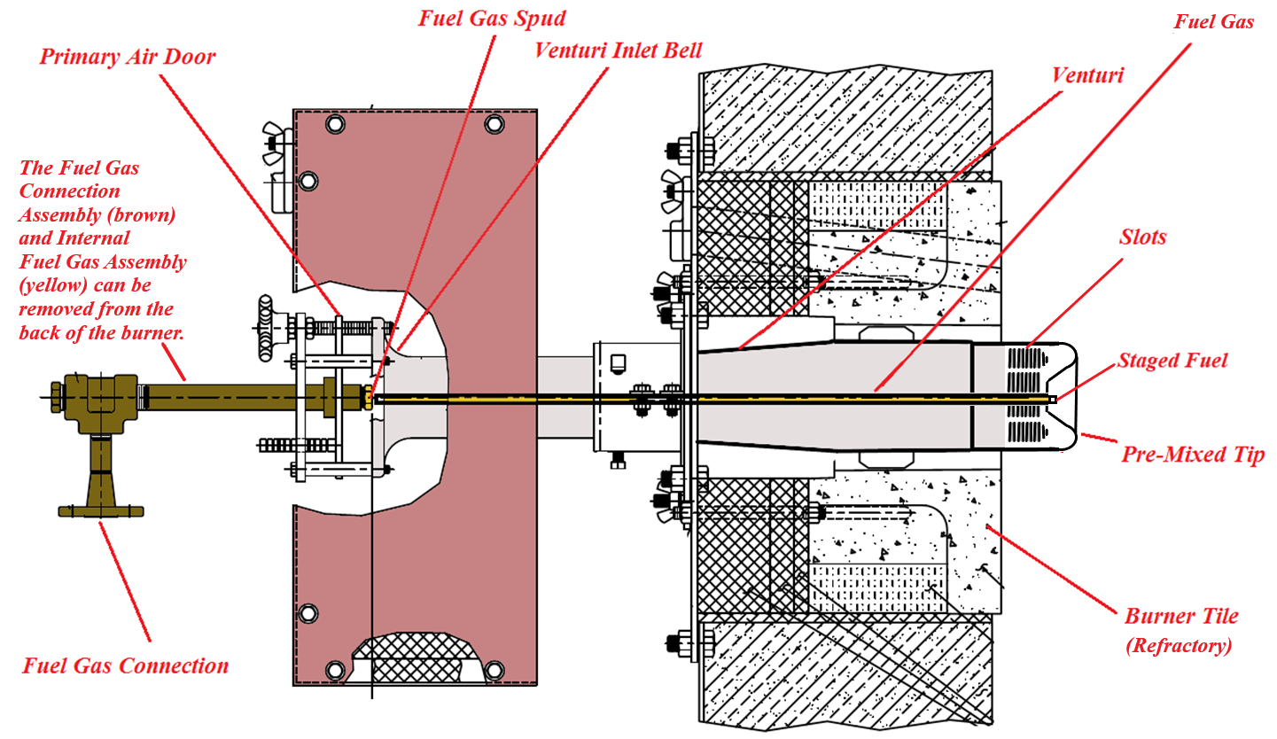
Figure 2. Zeeco RWSF burner with external fuel gas staging
The RWSF burner with external flue gas staging, shown in Figure 2, is used for applications that require the lowest NOx emissions. Since the staged fuel tip is external to the radiant wall burner tip, a true lean premixing of fuel gas and combustion air is achieved within the venturi before exiting through the tip slots. The external fuel gas is mixed with the surrounding products of combustion (flue gas), which dilutes the fuel gas before burning. The use of both lean premixing and staged fuel gas results in low thermal NOx emissions. Note, as for the RWSF burner with internal flue gas staging, the slots in the tip are also horizontal with respect to the end of the tip.
METHODOLOGY
In the following sections, we discuss in more detail the modifications to the gas spud, venturi, as well as tip design for the horizontal-slot wall burner.
Gas Spud Design
The gas spud is the device that ejects the fuel gas into the venturi. The fuel gas spud assembly is comprised of the fuel gas connection, a tee, the fuel gas spud, staged fuel gas riser, and staged fuel gas exit (staged fuel gas tip). The fuel gas spud assembly was designed for ease of maintenance. Since the staged gas riser is attached to the center of the fuel gas spud, both the fuel gas spud and the staged fuel gas riser can be removed at the same time for cleaning. This saves maintenance time and resources since many plants have thousands of radiant wall burners which need to be maintained.
Most staged fuel radiant wall burner spud designs require a primary spud and a staged spud. Multiple spuds require more time to remove if maintenance is needed resulting in increased costs. This burner design utilizes a single spud which includes the primary fuel gas port(s) and the staged fuel gas port(s). The new spud is in the same location as a standard primary fuel gas spud. Since the staged fuel gas port is in the center of the spud, the staged fuel gas riser on the center of the spud and then inserted through the venturi. In the event of required maintenance, the spud can be removed just like a standard radiant wall burner spud, but at the same time, the staged fuel riser is also removed. Thus, the primary and staged gas ports are all removed at the same time, reducing time and related maintenance costs.
Since the staged fuel port(s) is located in the center of the fuel gas spud, the same design can be used for two different types of staged fuel applications. The first type is Internal Staged Fuel which stages the fuel gas to some degree within the tip itself. This method is used for very high hydrogen applications and for projects with closer than usual burner-to-burner spacing. The second type is External Stage Fuel, where the staged tip located on the end of the staged gas riser extends through a center hole in the center of the tip. This method is used for the lowest NOx type applications since there are distinct lean premix zone and fuel-rich mixed with products of the combustion zone.
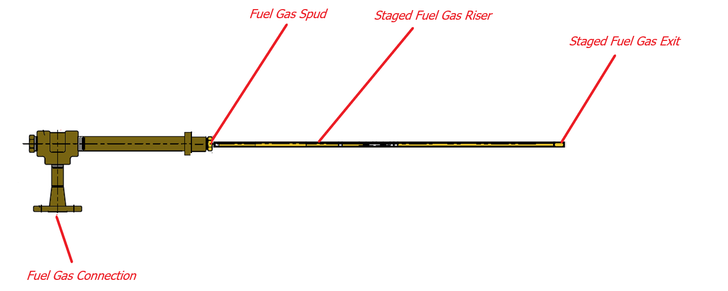
Figure 3. Schematic of the fuel gas spud assembly
Venturi Design
The development process started with new methods and ratios to match the size of the venturi inlet bell radius, throat diameter, straight section length, exit section angle, exit section length, and exit section diameter with the exit area of the tip. This matching is used to best utilize the fuel pressure to entrain combustion air through the venturi and out of the tip without limiting the airflow while maintaining enough internal tip pressure uniformity and therefore yields an optimal utilization of the venturi and tip configuration.
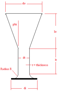
Figure 4. The above illustration of the venturi shows that the inlet (di) is matched with inlet radius (R), throat (dt), exit section length (lo) and the exit diameter (do)
Tip Design
Most of the development time was focused on the radiant wall burner tip design. Since the minimum internal tip pressure results in the lowest exit velocity, significant focus was placed on developing a uniform internal pressure to achieve uniform exit velocities. This is very important since the purpose of the burner design is to operate with high hydrogen fuels, which have faster flame velocities than methane, and areas of low exit velocity can result in premature flashback. Having more even internal tip pressures (resulting in more even exit velocities) allows more of the energy generated by the fuel gas to entrain additional combustion air to achieve leaner premixing.
Figure 5 shows the comparison between a tip with vertical slots and a tip with horizontal slots. For a burner with vertical slots, to keep the burner from flashing back with the wider range of exit velocities, the internal pressure needs to be increased to raise the lowest exit velocity above the flame speed of hydrogen to prevent flashback. As the vertical slot length increases, the velocity at the bottom of the slot decreases since the internal tip pressure distribution varies. This means that more of the energy produced from the fuel gas jet exiting the fuel gas spud needs to be used in the tip, which results in less availability to entrain combustion air. To make up for this, the amount of staged gas is typically reduced to increase the amount of primary gas to generate more energy to increase the internal pressures within the tip. The negative result of this is that the reduction in staged gas and the increase in primary gas makes the lean premixed zone more fuel rich and leaves less staged fuel gas to mix with flue gas, which results in higher thermal NOx emissions.
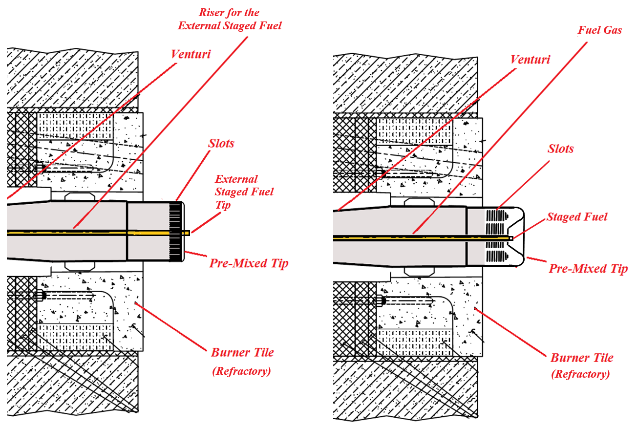
Figure 5. Comparison between a tip with vertical slots (left) and tip with horizontal slots (right)
Therefore, for applications that require long vertical slots, we determined that it would be better to use horizontal slots with an internal flow diverter to produce an even internal pressure distribution. The use of a flow diverter enables the slot design to be like what is used for lower heat release applications. To increase the slot flow area through the tip, more horizontal slots are added. This allows for the use of a uniform slot size that is less prone to flashback. In order to increase the flow area of the vertical slot tip, the slot length would need to get longer since the number of slots is limited by the diameter of the tip. Longer slots lead to more pressure variations which produce a wider range of exit velocities. Using a standard high hydrogen slot length and width along with an internal tip diverter produces more uniform internal tip pressures and allows the burner to be designed with more fuel gas staging and less primary fuel gas.
Part of the development process was to utilize computational tools to provide insight into the new tip design. We employed a wide range of computational techniques, from very detailed unsteady CFD (Computational Fluid Dynamics) simulations, to performing design exploration using steady-state simulations, as well as utilizing FEA (Finite Element Analysis) to evaluate and reduce the stresses in the tip.
RESULTS
Our initial CFD analysis was a transient analysis of flow through the venturi to capture the internal mixing inside the venturi and resolve the velocity profile as it exits the horizontal slots in the tip. The geometry utilized for this simulation is shown in Figure 6. This geometry did not include any internal or external staging. For this simulation, we utilized a mesh with over 60 million hexahedral (cubic) computational cells, refined near the spud and through the RWSF tip horizontal slots. The cell size varied between 100 m to 640 m throughout the simulation domain. We used a Large Eddy Simulation (LES) with Wall-Adaptive Local-Eddy (WALE) viscosity for this simulation with a time step of 0.0005 seconds, which was essential to resolve the necessary energy spectrum. The airflow rate of 0.144 kg/s and fuel flow rate of 0.008 kg/s correspond to heat release of 1.58 MMBTU/hr at 3% excess O2. We ran the simulation until we obtained a statistically steady state before starting sampling to obtain averaged results. Instantaneous and averaged fuel mixture and velocity contours are shown in Figure 7.
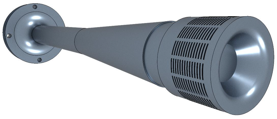
Figure 6. Simulation geometry of the venturi with horizontal slot RWSF burner
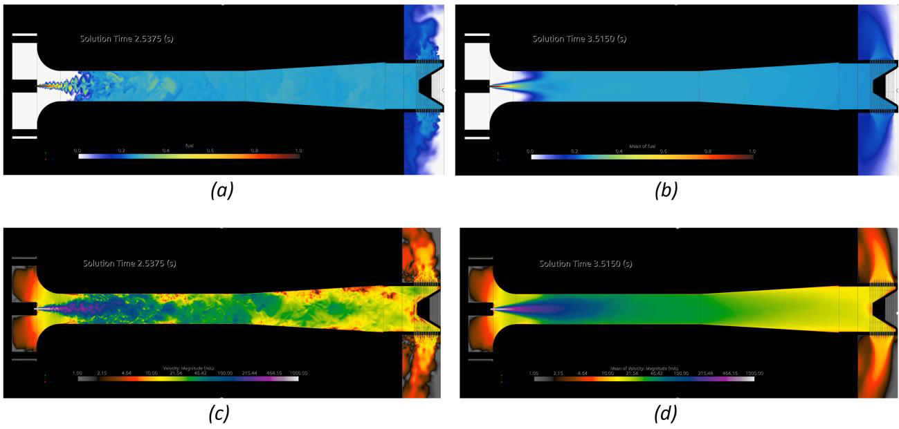
Figure 7. Results from the Large Eddy Simulation of the flow through the venturi and the RWSF tip at the center plane throughout the geometry: instantaneous (a) and averaged (b) fuel mixture profiles, and instantaneous (c) and averaged (d) velocity magnitude profiles.
Figure 8 shows the uniformity of averaged fuel mixture along the length of the venturi assembly. The planes showing the profiles are spaced every 10 cm. The uniformity of the fuel mixture was evaluated using the following formula:
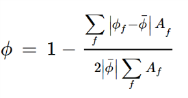
From Figure 8, it can be seen that the mixing for the simulated condition is very efficient, obtaining a surface uniformity of 0.998 approximately 30 cm into the venturi.
To explore and quantify the effect of the tip geometry on the burner performance, we created a parametric CAD model of the tip that could be used in the design exploration study. For this parametric model, we implemented fifteen design parameters and created twelve criteria to evaluate the performance of each design modification. Some of the design parameters defined the geometry of each slot (e.g., slot width, height, slot inlet profile), slot spacing, as well as interior dimensions of the burner tip. Additionally, we included operational parameters (e.g., mass flow) as the design parameters as well. For each design parameter, we set a range we wanted to explore. Some of the criteria used to evaluate the performance of the tip included the flow uniformity exiting the slots, pressure profile, and pressure drop. We used averaged fuel mixture, velocities, as well as turbulence quantities from the LES simulation at the exit plane of the venturi to define the inlet boundary conditions for a simplified axisymmetric model of the tip. For this design exploration study, we used the steady-state realizable k- turbulence model, with approximately one million cells per simulation. Figure 9 shows the simplified geometric domain used for the design exploration study, along with example results for the pressure and velocity profiles for one of the many designs.
Overall, we evaluated over 300 simulations with a different geometric combination of the design parameters to quantify the effect of both the geometric and operational parameters. As a result, we obtained a cross-correlation table that evaluates the Pearson correlation coefficient for a combination of any particular design parameter to any particular design objective. This type of analysis is very efficient in screening designs. Figure 10 shows a subset of the design parameters and design objectives that were used to analyze the effect of the design parameters on the performance of the tip. The strength of such design exploration studies is that they can be used to find correlations that may not be readily recognized if only one parameter was varied at a time. The Pearson correlation coefficient varies between -1 and 1, with -1 signifying an inverse relationship between any given design parameter and design objective, while 1 signifying a direct relationship between the quantities. A correlation coefficient of zero indicates that no correlation was found between the design parameter and the design objective.
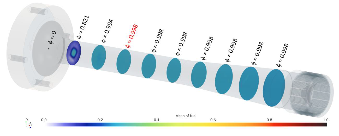
Figure 8. Averaged fuel mixture uniformity along the length of the venturi
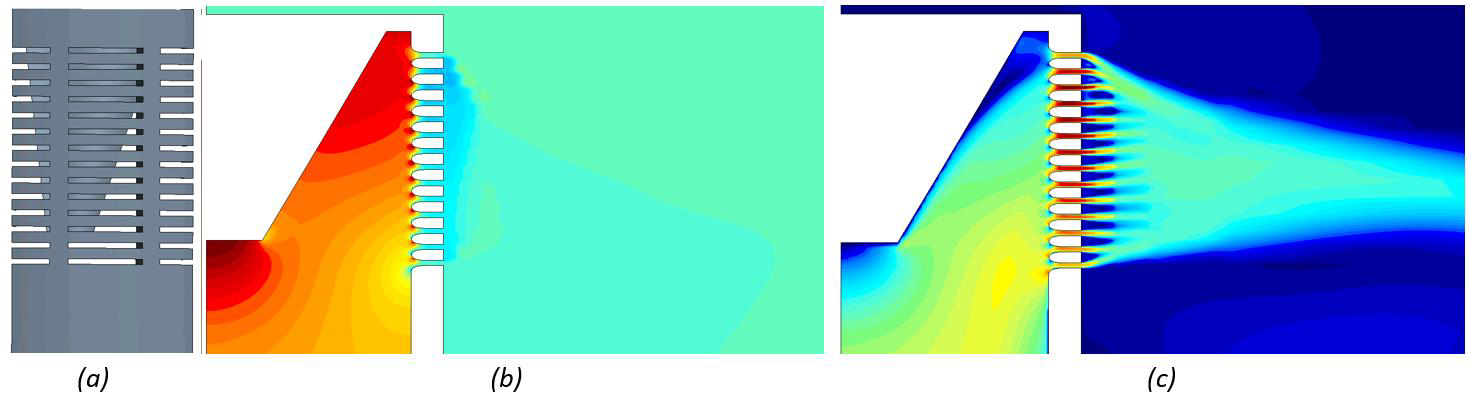
Figure 9. (a) Simplified geometry for one of the many hundreds of designs from the design exploration study. Pressure profile (b) along with a velocity magnitude profile (c). The profiles are shown at a plane that cuts through the middle of the slots.
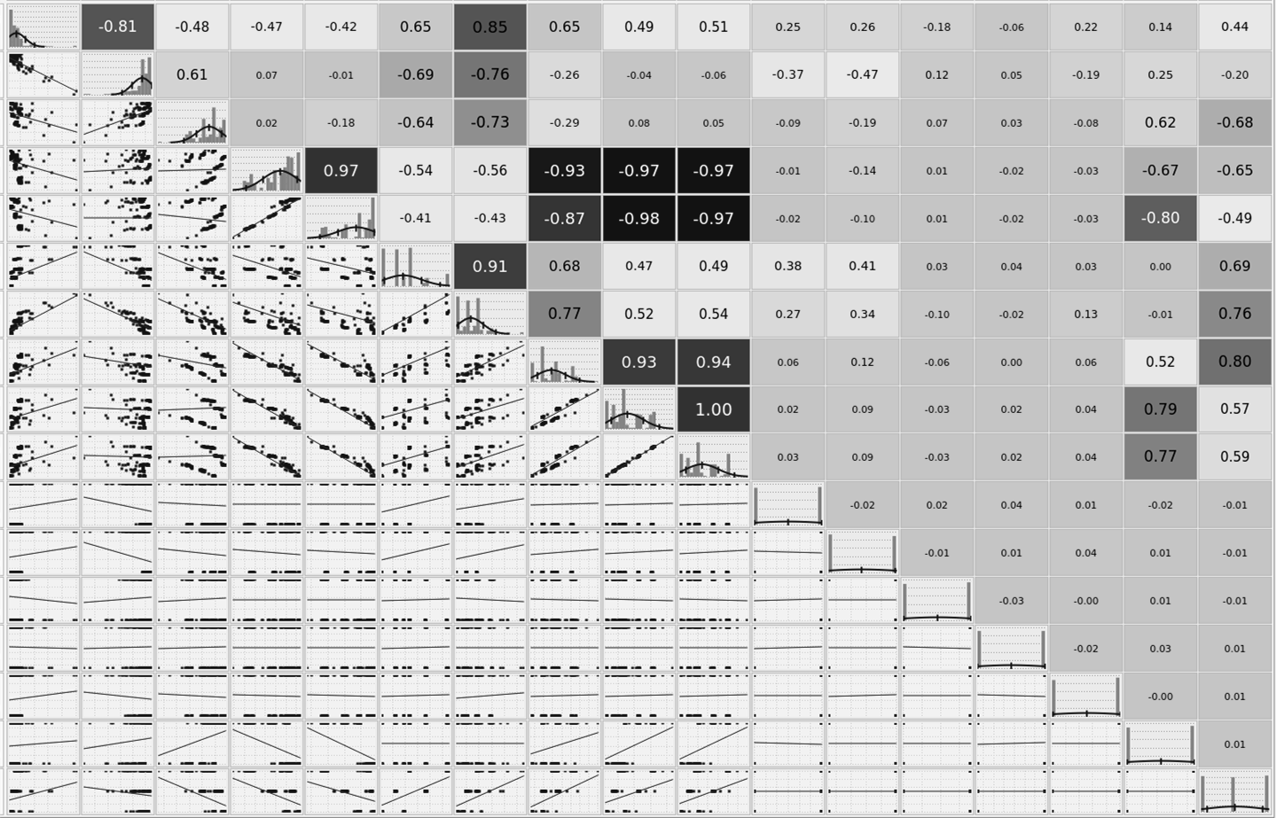
Figure 10. Cross-correlation of subset of geometric parameters and objectives used to explore the design space and its effect on the performance of radiant wall burner tip.
Using this analysis, we were able to identify that the interior shape of the tip end cap, as well as the slot inlet profiles, play a critical role in obtaining a uniform pressure distribution along the tip and uniform exit velocity from all slots.
Additionally, we also performed another design exploration study, but this time, the study was focused on the structural integrity of the radiant tip when subject to high heat fluxes inside the furnace. For this study, we used the solid tip and applied thermal load to the outside of the tip and convective heat transfer coefficient and temperature to the inside of the tip. The tip was constrained at the base, but otherwise, it was free to expand. For this analysis, we only solved the energy equation for the solid, with the finite element analysis to capture the stresses as a result of thermal loading. Using this simulation setup, we defined ten design parameters similar to those used for the design exploration study of the fluid flow, e.g., slot dimensions, spacing, tip end cap geometry, etc. For the design objectives, however, we created a new set of objectives that are relevant to the thermal and structural analysis, such as the maximum and minimum temperatures and their locations, temperature gradient, tip displacement (expansion), stresses throughout the tip, and their location.
For this design exploration study, we completed over 700 simulations that allowed us to explore the performance of the tip over a wide range of design parameters. A set of results for one such simulation is shown in Figure 11. For this particular design scenario, the temperature profiles indicate that the highest temperature is at the end cap of the tip, as expected; however, the heat is being conducted into the tip through the metal that is between the individual rows of slots. This results in lower stresses near the end cap, where we see the highest temperatures. The coolest region is in the middle of the slots, corresponding to a lower displacement. However, higher stresses could be addressed using different techniques given the relatively low temperatures. For this analysis, we have also created a cross-correlation table similar to that shown in Figure 11.
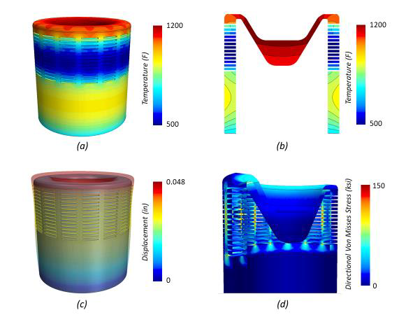
Figure 11. Thermal Finite Element Analysis of one of the hundreds of tip designs considered during the design exploration study. (a) The temperature profile of the tip, (b) with a vertical slice through the tip. (c) The predicted tip displacement, (d) and the associated Von Misses Stresses throughout the tip.
Based on the results of the computational analyses, we were able to identify the most critical design parameters and their impact on the performance of the radiant wall burner. Some of these parameters were then incorporated into the tip design, which we subjected to thorough testing at our test facility. Figure 12 shows the compact flame of the RWSF burner with internal staging firing natural gas during one of the test points. Select combustion test data for the RWSF burner with internal and external staging are captured in Table 1.
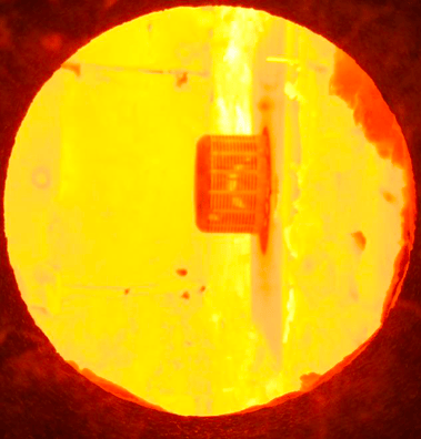
Figure 12: The above picture shows the Internal Staged version firing Natural Gas with a compact flame.
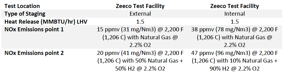
Table 1: Combustion Test Data for Zeeco RWSF Burner with Horizontal Slots
CONCLUSIONS
In this paper, we explored solutions to challenging radiant wall burner retrofit applications, along with our methodologies to not only improve the performance of the radiant wall burner but extend its life and increase the ease of maintenance. Both physical testing and the use of computational tools allowed us to explore new designs and predict the burner performance in challenging conditions over long periods of time. We coupled detailed transient simulations of the flow through the burner assembly with steady-state models, which allowed us to explore a wide range of design parameters and their effect on the performance of the burner. Furthermore, we studied the structural performance of the tip when subject to high radiant loads in the furnace and, through the use of design exploration, modified the design, so it is able more readily withstand these thermal loads. As the operating envelopes of radiant wall burners are pushed to their limits, with increased firing rates, high hydrogen fuels, or lower emissions, at Zeeco, we continue to use physical testing along with computational tools to drive innovation.