ABSTRACT
The use of ammonia as a fuel for industrial heating and steam generation is being considered in the industry as a potential option for reducing industrial greenhouse gas emissions, especially in regions (e.g., Japan, Korea) without indigenous natural gas and/or identified pore space for CO2 sequestration. Ammonia is a potentially attractive option as a lower carbon fuel solution because of: i) its energy density, which can result in greater transportability compared to hydrogen, ii) the existence of protocols, standards and infrastructure that can help enable the transportation of ammonia, and iii) the ability to potentially avoid additional facilities and energy consumption associated with the conversion from carrier medium (ammonia/hydrocarbon) to fuel (hydrogen).
Due to its relatively low laminar flame speed, sensitivity to velocity strain, narrow flammability range, and propensity to form high concentrations of nitrogen oxides (NOx), ammonia presents challenges as a fuel when compared with gaseous hydrocarbons and hydrogen-based fuels. This paper will describe the additional development of the burner designs and associated Computational Fluid Dynamics (CFD) capability tested and presented at the 2025 AFRC Industrial Combustion Symposium. As a result of these additional developments and works, a unique burner design based on Zeeco’s GLSF FREE JET platform specifically for use in forced-draft industrial heating and steam generation applications will be presented. Also described are improvements in the modeling tools and analytical methods that can allow for the prediction of ammonia burner performance in commercial applications.
The development work described in this paper is part of a larger ammonia combustion program sponsored by ExxonMobil including basic research by the Massachusetts Institute of Technology (MIT) and Stanford University aimed at furthering the understanding of ammonia combustion to allow for improved performance of an ammonia burner for commercial applications.
This paper will include data from tests of Zeeco’s modified GLSF FREE JET burner in forced-draft service with and without preheated air at different mixes of ammonia and hydrogen or natural gas at varying operating conditions, demonstrating progress on the development of a burner capable of providing a stable flame with NOx and ammonia emissions meeting target performance. It will also include supporting CFD analysis and a discussion of how CFD can be used to help predict combustion performance. This paper will reinforce that both combustion testing and CFD are essential for developing new technologies and predicting performance in commercial applications with reasonable certainty.
INTRODUCTION
Interest in ammonia combustion as a means to reduce CO₂ emissions is rising, particularly in regions lacking natural gas resources or CO₂ sequestration options. Ammonia offers high energy density, low carbon intensity, and established global infrastructure, making it more practical to store and transport than hydrogen. In addition, direct combustion of ammonia can avoid the energy and equipment required to crack it into hydrogen.
Early adoption is underway in Asian coal-fired power plants, where ammonia is being tested as a co-firing fuel to help lower CO₂ emissions. However, these systems still depend on Selective Catalytic Reduction (SCR) to help address thermal and fuel-bound NOx produced during ammonia combustion.
This program focuses on developing a commercial ammonia-fired burner suitable for both new and existing industrial heating applications. The objective is to create a fuel-flexible system that maintains stable operation under a wide variety of conditions while significantly reducing CO₂ emissions. Target performance includes NOx emission levels below 200 ppm (with a goal of <100 ppm) and ammonia (NH₃) slip below 50 ppm (preferably <10 ppm) at 3% O₂ dry. This paper outlines the progress achieved to date.
BURNER DEVELOPMENT, TESTING PLAN, AND TEST FACILITIES
Development and Testing Plan:
The ZEECO FREE JET® burner concepts were selected as the foundation for developing a commercial ammonia‑fired forced‑draft burner. Initial testing and configuration optimization were conducted on modified forced‑draft FREE JET burners, nominally rated at 4 MMBtu/hr, at Zeeco’s Global Technology Center near Tulsa, Oklahoma.
Computational Fluid Dynamics (CFD) model development is also a core element of the program. While combustion modeling for hydrocarbons and hydrogen is well established, ammonia kinetics and turbulence–chemistry interactions remain in early development. The CFD effort focuses on refining reaction mechanisms and turbulence models to more accurately represent ammonia combustion. The purpose is to develop reliable CFD tools that can support burner design and help predict performance in commercial applications.
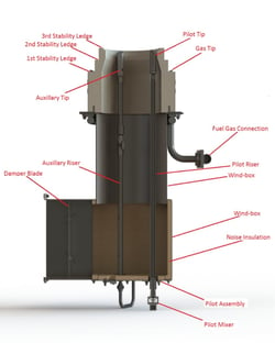
Figure 1: Standard Forced-draft GLSF FREE JET Burner.
Figure 1 shows the standard GLSF FREE JET Burner. The burner tested was modified for ammonia firing. All gas tips including the auxiliary tips fired the same fuel. The single pilot fired natural gas with a heat release of 90,000 Btu/hr. The GLSF FREE JET Burner is designed to be simple to operate, handles fuel transitions from 100% ammonia to 100% hydrogen to 100% natural gas, and any blends in between, while maintaining a stable flame. These burners are designed to operate between 10 to 20 years while offering the simplicity and stability required by users.
Test Facilities:
An existing Vertical Cylindrical (VC) single-burner test furnace at Zeeco’s Global Technology Center
was selected and modified to support ammonia firing. The furnace, appropriately sized for the 4
MMBtu/hr burner under evaluation, includes a radiant box approximately 17.33 ft tall with a
tube-to-wall distance of 5.83 ft. A single burner is mounted at the center of the furnace floor, and
firebox temperature is regulated through water-cooled tubes along one side of the VC, replicating the
heat-absorption characteristics of a commercial vertical cylindrical heater with multiple burners
arranged inside a ring of process tubes. Table 1 gives additional details about the test furnace used
in this work.
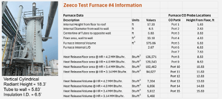
Table 1: Test Furnace Information
Ammonia-specific fuel supply, vaporization, piping, and metering systems were added or upgraded to ensure safe and reliable operation. A comprehensive safety review confirmed that facility safeguards, operating procedures, and personnel training were adequate to manage the hazards associated with ammonia handling and combustion. Operating protocols incorporated considerations such as personnel location, ambient conditions, wind speed and direction, and other factors necessary to ensure safe test execution.
Accurate emissions measurement required significant additional attention. Traditional chemiluminescence-based NOx analyzers can produce misleading results when NH₃ slip is present, due to chemical interferences within the analyzer. It was also necessary to quantify NH₃ slip and N₂O emissions to meet the program’s burner-development objectives. Although NOx measurements typically include only NO and NO₂, they do not account for N₂O, which is usually negligible—often below 5 ppm—in systems firing hydrocarbon or hydrogen fuels.
However, ammonia contains a high fraction of fuel-bound nitrogen, creating a potential for elevated N₂O formation. Historically, NO and NO2 were the main focus in relation to atmospheric ozone formation. Yet N₂O is a greenhouse gas, making its measurement and control important when ammonia is substituted as a lower GHG emission fuel.
For emissions measurement, the following analyzers were installed on the test furnace. These included:
- A Fourier Transform Infrared Spectroscopy (FTIR) system to measure NO, NO2, N2O, NH3, O2, H2O, CO2, and CO
- A Tunable Diode Laser (TDL) based system to measure NO, NH3, and H2O
- Chemiluminescent and paramagnetic type analyzers for NOx, NO2, O2 dry, and CO
CFD Methodology
The CFD modeling workflow leveraged the work developed for Year 1 of this program, for which the primary focus was natural draft burners1. With boilers appearing to be the primary near-term market opportunity for ammonia burner development, our focus shifted to forced-draft burners in Year 2. Forced-draft burners use a combustion-air fan and therefore require electric power, ducting, controls, and related equipment. They operate with a higher pressure drop, typically about 1 to 10 inches of H2O or more, but in return they can provide better mixing, staging, and flame stability to support lower NOx performance as compared to Natural Draft burners. Forced draft burners are common in boilers, and fired equipment that require high heat release, firing rate flexibility, very low emissions, wider turndown and tighter air/fuel controls.
The CFD methodology developed for this project was designed to meet the following objectives:
-
1.) Use the geometry and meshing capabilities of a commercial code for modeling actual burner and furnace geometries,
-
2.) Use detailed chemical kinetic mechanisms, at least in reduced form,
-
3.) Be able to change kinetic models quickly and easily,
-
4.) Allow for more than two independent reacting streams of fuel and oxidizer,
-
5.) Model participating-media thermal radiation effects,
-
6.) Be able to model chemical kinetic effects due to burner and furnace changes,
-
7.) Run a test furnace simulation with a single burner in about one day.
At the beginning of this project, a CFD capability meeting these requirements did not exist at Zeeco, nor based on a survey of available literature, anywhere in the burner industry. Combustion models commonly used in industry, such as Chemical Equilibrium, Eddy Break-Up (EBU), and Flamelet-based models, would not, without further development, meet the requirements for this project. University research codes use sophisticated chemistry along with Large Eddy Simulation (LES) models but are not designed to capture detailed burner and furnace geometries, especially with rapidly changing burner designs. While LES models are important to understand mechanisms behind combustion characteristics such as flame stability or blow off, they are computationally expensive and would not achieve the case turnaround needed for model validation and providing input to burner design and testing.
CFD Methodology Validation for Forced-Draft Burner Systems
An example of kinetic effects that are not captured by simpler models is shown in Figure 2. Thermal DeNOx chemistry, also known as ammonia reburning or Selective Non-Catalytic Reduction (SNCR)- is clearly visible as NO reacts with NH3 to form N2. The blue volume indicates NO destruction on the fuel-rich side of the flame, while the yellow volume indicates NO production on the lean side. The NO reduction shown in the blue zone is characteristic of ammonia combustion and does not occur in hydrocarbon-only combustion. This DeNOx behavior captured in its overall extent, is very sensitive to the geometric features of the underlying burner. For different burner configurations, it may not be as prominent.
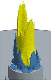
Figure 2: Iso-surfaces of NO creation rate = 0.05 kg/m3 sec (yellow) and NO destruction rate = 0.05 kg/m3 sec (blue).
Figure 3 shows a simulated visible flame surface approximated by an iso-surface of 1300 K temperature along with radiative flux to the cooling tubes as calculated by the Discrete Ordinates/Weighted Sum of Gray Gases (DO/WSGG). The DO/WSGG method, a mainstay of industrial combustion simulations, is entirely compatible with the current methodology.
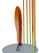
Figure 3: Iso-surface of T = 1300K and calculated radiative tube heat flux.
While single burner designs can be evaluated experimentally, CFD provides additional insight into flow structure, mixing, and localized reaction pathways that are difficult or impossible to measure. In this second year, CFD was used both as a predictive and a diagnostic tool to interpret experimental observations. This work establishes a validated baseline for future applications, including more complex burner arrangements, multi-burner furnaces, and extended fuel flexibility scenarios involving ammonia, hydrogen, and other fuels.
Figure 4 shows a reaction pathway analysis within a single CFD cell located inside the reaction zone. The complex chemical pathways leading to ammonia consumption and both NO production and destruction are seen to be active. This demonstrates the chemical kinetic detail included in these simulations.
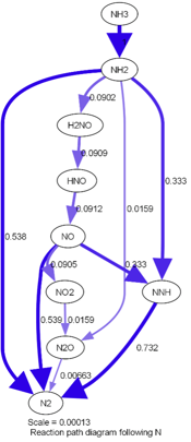
Figure 4: Chemical kinetic pathway analysis for a single CFD cell in the reaction zone.
Figure 5 shows results for the Rev 18 burner. Both models use the reduced mechanism based on the CRECK detailed mechanism2. This reduced mechanism was expanded from the 50-species model used in Year 1 work to improve the prediction of important pollutants NO2 and N2O. The CFD model gives good NO predictions and does a reasonable job predicting the onset of NH₃ slip as the fraction of ammonia in the fuel is increased in a forced-draft configuration, as shown in Figure 5. Predictions for N2O and NO2 are high for the CFD model, but trends are predicted very well.
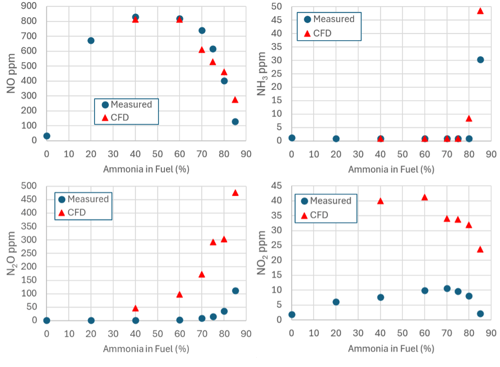
Figure 5: CFD results compared to FTIR measurements in a forced-draft burner fueled with ammonia mixed with natural gas.
The results of this CFD validation demonstrated that CFD is able to capture both the turbulence and chemical kinetics interactions with sufficient accuracy to be used as a predictive tool to help guide burner development.
After completing the development and validation of the CFD methodology for modeling both natural draft and forced-draft burners, CFD studies were conducted to explore the potential emission and flame stability benefits from a range of operating conditions and burner geometry modifications. Based on the potential for emission and slip reduction shown in the CFD simulations, several burner modifications and operating condition optimizations, namely, increased Air Preheat (APH) temperature, were tested. Selected results are presented in the subsequent section.
BURNER TEST RESULTS
Table 2 summarizes emissions measurements collected throughout the burner development program. For each test revision, key operating parameters—including heat release rate, combustion‑air temperature, and maximum ammonia firing percentage—are listed alongside raw emissions data for NH₃ slip, NO, and N₂O. All concentrations listed in Table 2 were measured using FTIR instrumentation.
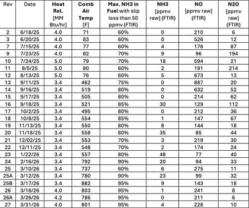
Table 2: Emissions measurements summary.
Because ammonia firing introduces unique measurement challenges, NH₃ slip values represent the maximum ammonia concentration achievable while maintaining slip below 50 ppmv. NO and N₂O values are reported as raw, dry concentrations. The dataset spans a wide range of operating conditions, including variations in heat release (3.4–5.0 MMBtu/hr), combustion‑air temperature (70–880°F), and ammonia firing percentage (60–95%), enabling evaluation of burner performance across the full design envelope.
Best Testing Results
Figure 6 illustrates the emissions measurements for burner Rev 25B, which gave the best results.
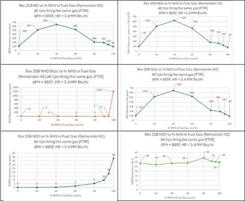
Figure 6: Emissions measurements for Rev 25B, which gave the best results.
Results and Discussion
A series of FTIR measurements was conducted at a constant heat release of 3.40 MMBtu/hr while varying the fuel composition from 100% hydrogen to 100% ammonia. The objective of this test sequence was to characterize how incremental increases in ammonia content influence emissions behavior—specifically NH₃ slip, NO, and N₂O formation—under otherwise fixed operating conditions. The results show clear and systematic trends that reflect the underlying combustion chemistry of hydrogen–ammonia mixtures.
Ammonia Slip
NH₃ slip remained negligible across all blends until ammonia became the dominant fuel component. For mixtures up to 95% NH₃, slip values were extremely low (0–9 ppm), indicating effective burnout and strong mixing under these conditions. However, at 100% ammonia, slip increased sharply to 1207 ppm, demonstrating the challenge of achieving complete conversion when no hydrogen is present to enhance flame speed and reaction kinetics. This behavior underscores the stabilizing role of hydrogen addition in ammonia combustion. The highest level of NH3 emissions was 9 ppmv, with less than 50 ppmv NH3 slip with a test fuel mixture of 95% NH3 & 5% H2. Testing at 96% NH3 & 4% H2, 97% NH3 & 3% H2, and 98% NH3 & 2% H2 would have helped generate a curve to determine the location where NH₃ slips actually broke the 50 ppmv level.
NO Emissions
NO emissions exhibited a strong dependence on ammonia concentration. With 100% hydrogen, NO was measured at 107 ppm, reflecting typical thermal‑NO formation in a hydrogen flame. As ammonia content increased, NO rose significantly, peaking at 644 ppm for the 60% NH₃ blend. This increase corresponds to the introduction of fuel‑bound nitrogen, which is readily oxidized to NO under high‑temperature conditions.
Interestingly, NO levels decreased at higher ammonia fractions, falling to 197 ppm at 90% NH₃ and 96 ppm at 100% NH₃. This decline suggests that as ammonia becomes the dominant fuel, lower flame temperatures and slower kinetics suppress NO formation despite the high nitrogen content. The result is a non‑monotonic NO trend: rising with initial NH₃ addition, then falling as the flame transitions to ammonia‑dominated behavior.
The best value of 143 ppmv NO emissions, where the NH3 slip was less than 50 ppmv, was at 95% NH3 & 5% H2.
N₂O Formation
N₂O emissions remained near zero for blends up to 60% NH₃, consistent with the rapid decomposition of N₂O at high flame temperatures. As ammonia concentration increased further, N₂O began to rise, reaching 10–18 ppm for the 90–95% NH₃ blends and 38 ppm at 100% NH₃. This trend reflects the shift toward cooler, slower‑reacting ammonia flames, where intermediate nitrogen‑oxide species such as N₂O are more stable. The highest level of N₂O emissions was 18 ppmv, with less than 50 ppmv NH3 slip, which was 95% NH3 and 5% H2.
The combined NO and N₂O behavior illustrates the classic tradeoff in ammonia combustion:
-
Hotter, hydrogen‑rich flames → high NO, negligible N₂O
-
Cooler, ammonia‑rich flames → lower NO, higher N₂O
Overall Interpretation
The fuel‑blend sweep demonstrates the complex interplay between flame temperature, reaction kinetics, and nitrogen‑conversion pathways in hydrogen–ammonia combustion:
-
Hydrogen‑rich blends produce high flame temperatures, resulting in high NO, negligible N₂O, and complete ammonia burnout.
-
Intermediate blends (40–60% NH₃) show the highest NO emissions, driven by both thermal and fuel‑bound nitrogen mechanisms.
-
Ammonia‑rich blends reduce NO formation but increase N₂O and NH₃ slip due to lower flame temperatures and slower kinetics.
-
Pure ammonia presents the greatest challenge, with high slip and elevated N₂O despite relatively low NO.
These results highlight the importance of fuel‑blend optimization, burner design, and temperature‑management strategies to balance NO, N₂O, and NH₃ slip when transitioning from hydrogen‑rich to ammonia‑dominant firing.
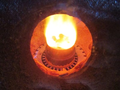
Figure 7: FREE JET firing 3.4 MM Btu/hr with 885F APH firing 100% ammonia.
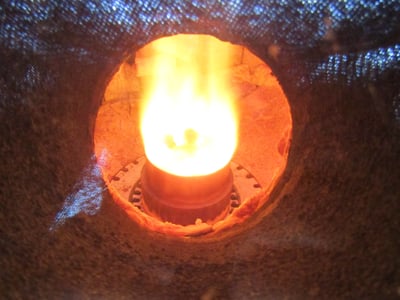
Figure 8: FREE JET firing 3.4 MM Btu/hr with 885F APH firing 95% ammonia and 5% hydrogen.
Air-Preheat Effects
Figure 9 illustrates the emissions ranges with differing APH temperatures with Rev 25A&B:
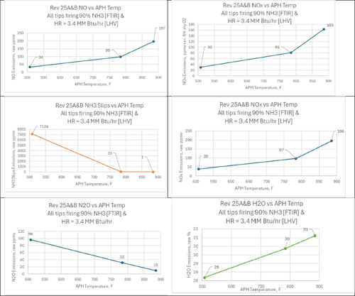
Figure 9: Emissions ranges with differing APH temperatures with Rev 25A&B.
Results and Discussion
Emissions testing was conducted at a constant heat release of 3.4 MMBtu/hr with a fuel blend of 90% ammonia and 10% hydrogen, while varying the APH temperature from approximately 500°F to 885°F. The FTIR measurements collected during Revisions 25A and 25B reveal clear and consistent relationships between APH temperature and the formation of NH₃ slip, NO, and N₂O.
Ammonia Slip Behavior
NH₃ slip exhibited a strong inverse dependence on APH temperature. At the lowest temperature tested (508°F), NH₃ slip was extremely high (over 7000 ppm), indicating incomplete fuel conversion under cooler combustion conditions. As APH temperature increased, slip decreased sharply, falling to 23 ppm at 784°F and reaching 1 ppm at 885°F. This trend reflects the improved reaction kinetics and enhanced burnout of unreacted ammonia at elevated temperatures. The results demonstrate that maintaining sufficiently high combustion‑air temperatures is essential for minimizing ammonia slip in high‑NH₃ firing applications.
NO Emissions
NO emissions increased steadily with rising APH temperature, consistent with the temperature‑dependent conversion of fuel‑bound nitrogen. At 508°F, NO was measured at 34 ppm, increasing to 99 ppm at 784°F and reaching 197 ppm at 885°F. This monotonic rise indicates that higher air‑preheat temperatures promote more complete oxidation of ammonia‑derived nitrogen species, leading to increased NO formation. The trend aligns with established ammonia‑combustion chemistry, where thermal and fuel‑bound nitrogen pathways intensify with temperature.
N₂O Formation
N₂O emissions displayed the expected peak‑and‑decline behavior characteristic of ammonia combustion. At the lowest APH temperature (508°F), N₂O was relatively high at 96 ppm, reflecting the formation of intermediate nitrogen‑oxide species under cooler conditions. As temperature increased, N₂O levels decreased significantly, dropping to 32 ppm at 784°F and 10 ppm at 885°F. This behavior is consistent with the thermal decomposition of N₂O at higher temperatures, where reaction pathways shift toward NO formation.
NO₂ Emissions
NO₂ concentrations remained near zero across all test points, indicating that nearly all oxidized nitrogen was present as NO or N₂O. This is typical for high‑temperature, fuel‑rich ammonia combustion environments where NO₂ formation is kinetically suppressed.
Overall Performance Trends
The combined results illustrate the competing effects of temperature on ammonia combustion:
-
Low APH temperature leads to high NH₃ slip, low NO, and elevated N₂O.
-
Intermediate temperatures reduce slip and N₂O while increasing NO.
-
High temperatures minimize slip and N₂O but produce the highest NO levels.
Higher APH temperatures lead to:
-
Higher NO formation.
-
Reduced NH3 emissions.
-
Reduced N2O emissions.
These findings highlight the importance of optimizing burner design and operating conditions to balance ammonia burnout, NO formation, and N₂O mitigation. The data provides a strong foundation for further refinement of strategies, staging concepts, and temperature‑control approaches to meet the program’s emissions targets.
CONCLUSION
The development and testing program demonstrated that ammonia can be successfully utilized as a fuel that can reduce CO₂ emissions in industrial heating applications when paired with a burner specifically engineered for its unique combustion characteristics. Through iterative design improvements, extensive testing, and advancements in CFD modeling, the modified GLSF FREE JET burner achieved stable operation across a wide range of ammonia–hydrogen blends and air-preheat conditions. The test results show that, with appropriate burner design and temperature management, the program’s target performance parameters can be met for NH₃ slip, NOx, and N₂O emissions under optimized conditions.
The combined experimental and modeling work confirms that both physical testing and CFD are essential tools for predicting ammonia-combustion performance. Continued refinement of burner geometry, fuel staging, and operating strategies can help support the transition from prototype to a commercially ready ammonia-fired burner, enabling a pathway to meaningful reductions in industrial CO₂ emissions.